Search Your Query

Custom Search

Wednesday, 1 June 2011

12V stroboscope


Summary of circuit features

  • Brief description of operation: Flashing light at adjustable speed, needs external trigger signal
  • Circuit protection: No special protection circuits used
  • Circuit complexity: Simple DC/AC converter and modified camera flashlight unit
  • Circuit performance: Works quite well
  • Availability of components: The problem is to find a suitable camera flas unit to modify, pulse transformer might be hard to find
  • Design testing: The orginal flash unit was modified until it worked as I want
  • Applications: Stroboscope effects, fast charging flash for camera
  • Power supply: 12V DC 1A power supply
  • Estimated component cost: No estimation made, I built my circuit from used components I had
  • Special notes: The stroboscope flash tube will overheat if used at high power settings for long time
  • Safety considerations: Electrical shock hazard, main capacitor has 500V charge and the trigger pulse is 4 kV, capacitors keep charge long time after the circuit is shut off, circuit should be built to a well insulating case

General information

This is one of my stroboscope designs. Usually many stoboscope circuit work directly from mains voltage, but this circuit uses 12V DC intead od mains AC. This is very good idea if you don't want to mess with direct mains voltage connected circuit or you want to run the stroboscope from batteries.
The circuit has some special functions compared to other stroboscope circuits found electronics books. First the there is a switch for selecting the flash power: with C3 you can get very fast flash rates (over 50 Hz), C2 is most suitable for normal operation and using C1 directly you get very bright single flashes.
The stroboscope circuit does not include any timing circuit of it's own. The strobocope will flash when a suitable voltage pulse is applied to the strigger input. This trigger source can be a small variable frequency oscillator, music source or a special strobo controller

How the circuit works

The stoboscope tube needs about 250-400V DC to operate. This high voltage is generated using simple voltage step up circuit built from transistors Q1,Q2 and transformer T1. This circuit gives out about 230V AC voltage which is then rectified with rectifying bridge U1 (must have at least 400V voltage rating) and stored to the main capacitor C1.
I built my stroboscope from parts taken from old camera flash unit. This approach gave me nice flash tube with reflector, trigger transformer and some of the capacitors (for example C1). Other parts were the one luying around. I used some strange triac I found in my for the triggering circuit, but any triac which can handle at least 1A and 400V should do the job well.
Circuit diagram of the stoboscope
CAUTION - high voltage of strobes can cause a nasty and possibly fatal shock. The energy storage capacitor can retain dangerous high voltage after power is removed from the board.

What is the available flash energy ?

The power available from the circuit depends on the capacitor selected. The capacitors are fully loaded when they reach 350V, so the different capacitors give the following power ratings:
Capacitor  Flash energy       Max. speed    Max. power to tube
C1 9 Ws 2 Hz 20 W
C2 0.3 Ws 40 Hz 12 W
C3 0.06 Ws 80 Hz 5 W

Warnings !

Read the following warnings carefully before even thinking of building this circuit:
When the circuit operates there are dangerously high voltages in the circuit. Do not in any case get in contact with live circuit. The charge in the main capacitor can give you very nasty electric shock and are even capable of killing.
And remeber that thew main capacitors will keep their high voltage charges long time after you have switched off the circuit because there is no bleeding resistors (you can add your own if you wish, just wire 1Mohm resistors in parallel with C1, C2 and C3).
Make sure that you have some plastic shield (transparent plastic) in front of the flash tube all the time. If the power rating of the flash tube is exceeded or the flash tube is damaged the flash tube can explode. A plastic shield in front of the flash tube will make sure that the flying pieces of glass will not damagen anybody.
Because the capacitor charging circuitry is more powerful than in the original flash unit the flash tube might get more average power than it is designed to handle. It is possible that the flash tube can overheat because of this.
Do not connect the power supply in the wrong way because this can damage the power transistors and/or the transformer T1. It might be a good idea to add a diode to the power input to make sure that you can't connect the power in the wrong way to the circuit.
Do not look directly to the flash tube at short distances. The flashes generated by this circuit are very bright (as bright as the original camera flash in high power mode). Those flashes can temporarily blind you if you are too near to the circuit.


Component list

R1   1.2 kohm 1/2W
R2 1.2 kohm 1/2W
R3 120 ohm 2W
R4 10 kohm 1/2W
C1 100..150 uF 400V flash capacitor (from camera flash unit)
C2 4.7 uF 400V
C3 1 uF 400V
CZ 33 nF 400V
Q1 2N5983 NPN power transistors
Q2 2N5983 NPN power transistors
Q3 MAC216-4 Triac
TUBE Xenon flash tube (taken from camera flash unit)
T1 220V to 2x9V transformer, at least 10W power rating
T2 Xenon flash tube trigger transformer (from camera flash unit)
T3 Thyristor trigger transformer with good isolation
U1 Rectifier 1A 400V (can be build from four 1N4007 diodes)
S1 Switch one of three, at least 2A 400V rating

Car Battery Charger

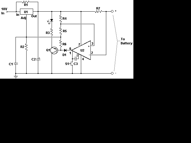
This charger will quickly and easily charge most any lead acid battery. The charger delivers full current until the current drawn by the battery falls to 150 mA. At this time, a lower voltage is applied to finish off and keep from over charging. When the battery is fully charged, the circuit switches off and lights a LED, telling you that the cycle has finished.

Schematic:

This is the schematic of the Car Battery Charger

Parts:                                                           


Part
Total Qty.
Description
R1
1
500 Ohm 1/4 W Resistor
R2
1
3K 1/4 W Resistor
R3
1
1K 1/4 W Resistor
R4
1
15 Ohm 1/4 W Resistor
R5
1
230 Ohm 1/4 W Resistor
R6
1
15K 1/4 W Resistor
R7
1
0.2 Ohm 10 W Resistor
C1
1
0.1uF 25V Ceramic Capacitor
C2
1
1uF 25V Electrolytic Capacitor
C3
1
1000pF 25V Ceramic Capacitor
D1
1
1N457 Diode
Q1
1
2N2905 PNP Transistor
U1
1
LM350 Regulator
U2
1
LM301A Op Amp
S1
1
Normally Open Push Button Switch
MISC
1
Wire, Board, Heatsink For U1, Case, Binding Posts or Alligator Clips For Output


Notes:
  1. The circuit was meant to be powered by a power supply, which is why there is no transformer, rectifier, or filter capacitors on the schematic. There is no reason why you cannot add these.
  2. A heatsink will be needed for U1.
  3. To use the circuit, hook it up to a power supply/plug it in. Then, connect the battery to be charged to the output terminals. All you have to do now is push S1 (the "Start" switch), and wait for the circuit to finish.
  4. If you want to use the charger without having to provide an external power supply, use the following circuit.

    This is the schematic of the Car Battery Charger Power Supply
    Part
    Total Qty.
    Description
    Substitutions
    C1
    1
    6800uF 25V Electrolytic Capcitor
    T1
    1
    3A 15V Transformer
    BR1
    1
    5A 50V Bridge Rectifier
    10A 50V Bridge Rectifier
    S1
    1
    5A SPST Switch
    F1
    1
    4A 250V Fuse

    5.The first time you use the circuit, you should check up on it every once and a while to make sure that it is working properly and the battery is not being over charged.

Tuesday, 31 May 2011

Automatic Load Sensing Power Switch

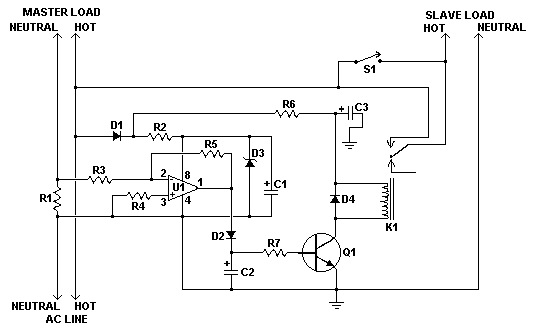
This circuit will automatically switch on several mains-powered "slave" loads when a "master" load is turned on. For example, it will switch on the amplifier and CD player in a stereo system when the receiver is turned on. It works by sensing the current draw of the "master" device through a low value high wattage resistor using a comparator. The output of that comparator then switches on the "slave" relay. The circuit can be built into a power bar, extension cord or power center to provide a convenient set of "smart" outlets that switch on when the master appliance is powered (turn on the computer monitor and the computer, printer and other peripherals come on as well).

Schematic:

Schematic for Automatic Load Sensing Power Switch


Parts: 

Part
Total Qty.
Description
C1, C3
2
10uF 35V Electrolytic Capacitor
C2
1
1uF 35V Electrolytic Capacitor
R1
1
0.1 Ohm 10W Resistor
R2
1
27K 1/2W Resistor
R3, R4
1
1K 1/4W Resistor
R5
1
470K 1/4W Resistor
R6
1
4.7K 1/2W Resistor
R7
1
10K 1/4W Resistor
D1, D2, D4
3
1N4004 Rectifier Diode
D3
1
1N4744 15V 1 Watt Zener Diode
U1
1
LM358N Dual Op Amp IC
Q1
1
2N3904 NPN Transistor
K1
1
Relay, 12VDC Coil, 120VAC 10A Contacts
S1
1
SPST Switch 120AVC, 10A
MISC
1
Board, Wire, Socket For U1, Case, Mains Plug, Socket

 Notes:


  1. This circuit is designed for 120V operation. For 240V operation, resistors R2 and R6 will need to be changed.
  2. A maximum of 5A can be used as the master unless the wattage of R1 is increased
  3. S1 provides a manual bypass switch.
  4. THis circuit is not isolated from the mains supply. Because of this, you must exercise extreme caution when working around the circuit if it is plugged in.

12V to 120V Inverter


Schematic:

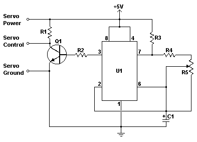
Schematic for the servo controller

Parts:

Part
Total Qty.
Description
C1, C2
2
68 uf, 25 V Tantalum Capacitor
R1, R2
2
10 Ohm, 5 Watt Resistor
R3, R4
2
180 Ohm, 1 Watt Resistor
D1, D2
2
HEP 154 Silicon Diode
Q1, Q2
2
2N3055 NPN Transistor (see "Notes")
T1
1
24V, Center Tapped Transformer (see "Notes")
MISC
1
Wire, Case, Receptical (For Output)

Notes:

  1. Q1 and Q2, as well as T1, determine how much wattage the inverter can supply. With Q1,Q2=2N3055 and T1= 15 A, the inverter can supply about 300 watts. Larger transformers and more powerful transistors can be substituted for T1, Q1 and Q2 for more power.
  2. The easiest and least expensive way to get a large T1 is to re-wind an old microwave transformer. These transformers are rated at about 1KW and are perfect. Go to a local TV repair shop and dig through the dumpster until you get the largest microwave you can find. The bigger the microwave the bigger transformer. Remove the transformer, being careful not to touch the large high voltage capacitor that might still be charged. If you want, you can test the transformer, but they are usually still good. Now, remove the old 2000 V secondary, being careful not to damage the primary. Leave the primary in tact. Now, wind on 12 turns of wire, twist a loop (center tap), and wind on 12 more turns. The guage of the wire will depend on how much current you plan to have the transformer supply. Enamel covered magnet wire works great for this. Now secure the windings with tape. Thats all there is to it. Remember to use high current transistors for Q1 and Q2. The 2N3055's in the parts list can only handle 15 amps each.
  3. Remember, when operating at high wattages, this circuit draws huge amounts of current. Don't let your battery go dead :-).
  4. Since this project produces 120 VAC, you must include a fuse and build the project in a case.
  5. You must use tantalum capacitors for C1 and C2. Regular electrolytics will overheat and explode. And yes, 68uF is the correct value. There are no substitutions.
  6. This circuit can be tricky to get going. Differences in transformers, transistors, parts substitutions or anything else not on this page may cause it to not function.
  7. If you want to make 220/240 VAC instead of 120 VAC, you need a transformer with a 220/240 primary (used as the secondary in this circuit as the transformer is backwards) instead of the 120V unit specified here. The rest of the circuit stays the same. But it takes twice the current at 12V to produce 240V as it does 120V.
  8. Check out this forum topic to answer many of the most commonly asked questions about this circuit: 12 - 120V Inverter Again. It covers the most common problems encountered and has some helpful suggestions.

AC Motor Speed Controller

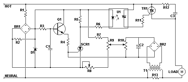
This AC motor speed controller can handle most universal type (brushed) AC motors and other loads up to about 250W. It works in much the same was a light dimmer circuit; by chopping part of the AC waveform off to effectively control voltage. Because of this functionality, the circuit will work for a wide variety of loads including incandescent light bulbs, heating elements, brushed AC motors and some transformers. The circuit tries to maintain a constant motor speed regardless of load so it is also ideal for power tools. Note that the circuit can only control brushed AC motors. Inductive motors require a variable frequency control.


Schematic:

Schematic of the AC Motor Controller

Parts:

Part
Total Qty.
Description
1
1
27K 1W Resistor
R2
1
10K 1/4W Resistor
R3
1
100K 1/4W Resistor
R4
1
33K 1/4W Resistor
R5
1
2.2K 1/4W Resistor
R6
1
1K 1/4W Resistor
R7
1
60K Ohm 1/4W Resistor
R8
1
3K Linear Taper Trim Pot
R9
1
5K Linear Taper Pot
R10
1
4.7K Linear Taper Trim Pot
R11
1
3.3K 1/4W Resistor
R12
1
100 Ohm 1/4W Resistor
R13
1
47 Ohm 1W Resistor (See Notes)
C1, C3
2
0.1uF Ceramic Disc Capacitor
C2
1
100uF 50V Electrolytic Capacitor
D1
1
6V Zener Diode
Q1
1
2N2222 NPN Transistor
SCR1
1
ECG5400
TR1
1
TRIAC (See Notes)
U1
1
DIAC Opto-Isolator (See Notes)
BR1, BR2
2
5A 50V Bridge Rectifier
T1
1
Transformer (See Notes)
MISC
1
PC Board, Case, Line Cord, Socket For U1, Heatsinks

Notes:

  1. TR1 must be chosen to match the requirements of the load. Most generic TRIACs with ratings to support your load will work fine in this circuit. If you find a TRIAC that works well, feel free to leave a comment.
  2. U1 must be chosen to match the ratings of TR1. Most generic DIAC based opto-isolators will work fine. If you have success with a specific part, feel free to leave a comment.
  3. T1 is any small transformer with a 1:10 turns ratio. The circuit is designed to run on 120V so a 120V to 12V transformer will work. Alternately, you can wind T1 on a transformer core using a primary of 25 turns, a secondary of 200 turns, and 26 gauge magnet wire.
  4. R9 is used to adjust motor speed. R10 is a trim pot used to fine tune the governing action of the circuit. R8 fine tunes the feedback circuit to adjust for proper voltage at the gate of SCR1. It should be adjusted to just past the minimum point at which the circuit begins to operate.
  5. R13 must be chosen to match the load. Generally, larger loads will require a smaller value.
  6. Since this circuit is not isolated from mains, it must be built in an insulated case.
Related Posts Plugin for WordPress, Blogger...