Search Your Query

Custom Search
Showing posts with label Power and Motor. Show all posts

Tuesday, 31 May 2011

AC Motor Speed Controller

This AC motor speed controller can handle most universal type (brushed) AC motors and other loads up to about 250W. It works in much the same was a light dimmer circuit; by chopping part of the AC waveform off to effectively control voltage. Because of this functionality, the circuit will work for a wide variety of loads including incandescent light bulbs, heating elements, brushed AC motors and some transformers. The circuit tries to maintain a constant motor speed regardless of load so it is also ideal for power tools. Note that the circuit can only control brushed AC motors. Inductive motors require a variable frequency control.
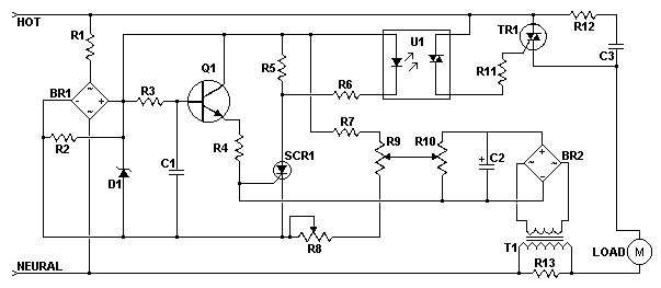


Schematic:

Schematic of the AC Motor Controller

Parts:

Part
Total Qty.
Description
1
1
27K 1W Resistor
R2
1
10K 1/4W Resistor
R3
1
100K 1/4W Resistor
R4
1
33K 1/4W Resistor
R5
1
2.2K 1/4W Resistor
R6
1
1K 1/4W Resistor
R7
1
60K Ohm 1/4W Resistor
R8
1
3K Linear Taper Trim Pot
R9
1
5K Linear Taper Pot
R10
1
4.7K Linear Taper Trim Pot
R11
1
3.3K 1/4W Resistor
R12
1
100 Ohm 1/4W Resistor
R13
1
47 Ohm 1W Resistor (See Notes)
C1, C3
2
0.1uF Ceramic Disc Capacitor
C2
1
100uF 50V Electrolytic Capacitor
D1
1
6V Zener Diode
Q1
1
2N2222 NPN Transistor
SCR1
1
ECG5400
TR1
1
TRIAC (See Notes)
U1
1
DIAC Opto-Isolator (See Notes)
BR1, BR2
2
5A 50V Bridge Rectifier
T1
1
Transformer (See Notes)
MISC
1
PC Board, Case, Line Cord, Socket For U1, Heatsinks

Notes:

  1. TR1 must be chosen to match the requirements of the load. Most generic TRIACs with ratings to support your load will work fine in this circuit. If you find a TRIAC that works well, feel free to leave a comment.
  2. U1 must be chosen to match the ratings of TR1. Most generic DIAC based opto-isolators will work fine. If you have success with a specific part, feel free to leave a comment.
  3. T1 is any small transformer with a 1:10 turns ratio. The circuit is designed to run on 120V so a 120V to 12V transformer will work. Alternately, you can wind T1 on a transformer core using a primary of 25 turns, a secondary of 200 turns, and 26 gauge magnet wire.
  4. R9 is used to adjust motor speed. R10 is a trim pot used to fine tune the governing action of the circuit. R8 fine tunes the feedback circuit to adjust for proper voltage at the gate of SCR1. It should be adjusted to just past the minimum point at which the circuit begins to operate.
  5. R13 must be chosen to match the load. Generally, larger loads will require a smaller value.
  6. Since this circuit is not isolated from mains, it must be built in an insulated case.

Tuesday, 24 May 2011

Imagine A Power Source That ... Powers Itself


Imagine A Power Source That ... Powers Itself
Backup generators are noisy and add pollutants to our air. They are also expensive and not very dependable when looking at long stretches of power outages. No wonder why some people think twice about spending $500 and upward to have a piece of equipment that collects dust most of the time.


A new company in Italy called Electro Power Systems SpA has been designing a useful alternative back up power that is clean and reliable since their inception in 2005. Last year, this unit called the ElectroSelf™ began receiving the praise that it deserved.

ElectroSelf™ is a self-contained and self-recharging fuel-cell system that runs solely on water. There are no batteries, no diesel fumes or any other type of expensive and inconvenient factors to contend with. ElectroSelf leverages the water that is produced by the fuel cell during a power outage to generate clean H2, feeding the fuel cell during the next unscheduled power shortage.

This unit can also be incorporated with a main power source in an on grid and placed anywhere in the world. For the prospect of selling power back to utility companies in very rural country, this potential is very possible. As a self-contained unit, the ElectroSelf is capable of operating in temperatures ranging between -20 degrees C to 45 degrees C, indoors or out. Forming a business from a community co-op can also become a reality within the proper realms.

Adriano Marconetto is founder and CEO of Electro Power Systems SpA and anticipates green networks such as his company have introduced to become increasingly attractive to alternative fuels already in place. The fact that ElectroSelf is 100% self-sufficient in creating its own hydrogen opens doors for other companies to search out more flexible and totally green designs in all aspects of fuel free energy.

Not only is this new design virtually maintenance free and guaranteed to return upfront costs but is also a very real option for disaster areas, areas of extreme temperatures and isolated regions. Operating costs are minimal because of the absence of moving parts and topping off with water once per year is the only regular requirement.

ElectroSelf™ was included in the Global Cleantech 100 of 2009 and at the GSMA's Mobile Innovation EMEA event in June 2009, ElectroSelf was awarded "Most Innovative Product Enabling a Greener World". This is a fascinating use of green energy by combining Hydrogen (H2) and Oxygen (O2) to create energy; hydrogen fuel by electrolysis of demineralised wastewater of the power generation phase.

Each day, innovators from around the world are creating alternative methods to aid our planet while allowing us to hold on to the luxuries that we have become accustomed to. Hydrogen fuel by electrolysis is just the first step to bigger and better energy creativity to come.

Image credit: Electro Power System Sps 

Web: (electrops.it) 


Discrete component motor direction controller


 This circuit can control a small DC motor, like the one in a tape recorder. When both the points A & B are "HIGH" Q1 and Q2 are in saturation. Hence the bases of Q3 to Q6 are grounded. Hence Q3,Q5 are OFF and Q4,Q6 are ON . The voltages at both the motor terminals is the same and hence the motor is OFF. Similarly when both A and B are "LOW" the motor is OFF.
When A is HIGH and B is LOW, Q1 saturates ,Q2 is OFF. The bases of Q3 and Q4 are grounded and that of Q4 and Q5 are HIGH. Hence Q4 and Q5 conduct making the right terminal of the motor more positive than the left and the motor is ON. When A is LOW and B is HIGH ,the left terminal of the motor is more positive than the right and the motor rotates in the reverse direction. I could have used only the SL/SK100s ,but the ones I used had a very low hFE ~70 and they would enter the active region for 3V(2.9V was what I got from the computer for a HIGH),so I had to use the BC148s . You can ditch the BC148 if you have a SL/SK100 with a decent value of hFE ( like 150).The diodes protect the transistors from surge produced due to the sudden reversal of the motor.

 Click here for the circuit diagram

Monday, 23 May 2011

Super Flux RGB LED Controller


ntroduction

 
In this project it was used the “Piranha Super-flux RGB” Led of common 
anode, and the PIC18F25K20, in order to generate combinations of colors. 
It has two function modes, automatic that generate the color sequence 
that is stored in the μC memory, and the manual mode in which you can 
select one of the seven possible colors.

Schematic


Firmware
 
The control of the RGB led is made with PWM(Pulse With Modulation), 
because PIC18F25K20 only have 2 PWM outputs (Hardware), I did the 
PWM by software to have 3 PWM outputs for that I use TIMER0 and for 
the Manual mode I use IOC(interrupt on change).
 
De-bounce

In this project I use push buttons to change between modes and to 
change the colors. But if we use the button as in the circuit (1) we 
have a problem. The problem with this configuration, due to the 
mechanical nature of any switch that may contains spring return 
action of some kind, there won’t be a clean transition from a state 
to another, but instead there will be a series of high and low states 
spikes. To solve that problem we have to implement a de-bouncing 
system, it can be done by hardware or software. We can use a RC 
delay circuit or it can be done with a schmitt trigger, but both ways 
will increase the price. So I done by software the de-bounce.
Example of code to do de-bounce:


It can be done in a different away but this way works for me.

PSU
I use a 7812 voltage regulator to keep the voltage stable in the RGB led and for 
μC I use an LM317 voltage Regulator. To calculate the output of LM317 I use this equation:


Led RGB
I use different resistor values on the RGB Led because which color have a different 
VF (Forward Voltage) in order to have the same LUX for each color. To calculate 
the resister I use these equations:


Download

A Very Simple Power Failure Light


Introduction


This is a very basic power failure lighting circuit based around a relay.
This simple circuit has many uses, from lighting up rooms and walkways in the case of 
a power failure, to monitoring and security uses.
There are many different power failure circuits out there based on 555 
timers or transistors but they all have different problems including limited 
input voltage, price and complexity, and poor backup power. This unit has 
been designed to work with mains power all the way down to 5 volts, and 
power 3 LEDs to provide light for a hallway or a child's room in the event 
of power failure. The PCB includes many simple add-ons and modifications 
too. 
Specs 
Input Voltage Max: 240 Volts AC
Input Voltage Min: 5 Volts DC
Approximant Power Consumption: 450 mW


Schematic


Explanation
This circuit is connected to ac power through J1 then rectified to dc through 
D1-D4. D5 is a 12 volt zener diode being used along with the resistor R1 
and the coil resistance of relay RL1 to regulate the input voltage to 12 volts 
and C1 is used to help smooth this power.

Alternatively a dc voltage of 5 volts or more can be connected directly to J2 
and J3, positive to J2 and negative to J3; in this setup the circuit would not 
need J1D1-D5, and R1.
The relay RL1 is a SPDT 5vDc relay and when power is applied to it, it opens 
the circuit with the LEDs so they are off as long as power is on if the power 
goes off, the relay closes the circuit and the battery BAT1 powers the LEDs 
D6D7, and D8. In this circuit BAT1 is a 9 volt battery that powers the 
3 LEDs through R3; however BAT1 can be many different batteries depending 
on your needs. J4 is also available in parallel with the LEDs to connect a
buzzer or etc.

You can also put a switch on one of the wires for BAT1 so you can turn it 
off so that you 
don't drain it when the circuit is not being used.
Parts List


1
R1
1.2k Ohm
1
R3
120 Ohm
1
C1
470uF
4
D1-D4
1N4004
1
D5
1N4742A
3
D6-D8
White LED
1
RL1*
5 Volt SPDT Relay T7CV5D-05
1
BAT1
9V
1
-
9V Battery Connector

*There are many different relays that can be used, some that even use 
next to no power.
PCB


Download

Motorized Curtain with Remote control


Introduction


The project is "Motorized Curtain" with Remote control. It is made 
up of MCU ATMEGA328 with Arduino BootLoader, motor driver L293D 
( i used L293B with external diodes, because i couldn't find L293D ), 
IR Receiver TSOP 1738, DC Motor from an old printer and other 
small parts. To control it, i use IR remote control from a PixelView 
TV Tuner. The software allows moving the curtain from left to right 
and back, or on steps. On the last peg (of the curtain rail) is 
attached a small magnet, which interacts with the two reed 
contacts, placed on the two ends of the rail. The last peg is 
moved by a cord, which connects it to the motor on one side 
and a reel to the other.
Source Code is written on Arduino. I use NECIRRcv Libraries for decode 
code from IR Remote Control.

Schematic


Photos


Download
Related Posts Plugin for WordPress, Blogger...