Search Your Query

Custom Search

Wednesday 1 June 2011

How to construct a Infra Red Wireless Door Monitor


Door Monitor Project
This door monitor project uses an infrared beam to monitor door & passageways or any other area. When the beam is broken a relay is tripped which can be used to sound a bell or alarm. Suitable for detecting customers entering a shop, cars coming up a driveway, etc. The IR beam is very strong. Distances over 25 feet can be monitored. A 12V DC supply is required to power the circuit. A 12V wall adaptor is fine.
Provision has been made so that only one power supply needs to be used to power both units. The relay is rated to switch mains voltages.
Door Monitor Transmitter Board


The door monitor transmitter board consists of two square-wave oscillators, one running at approx. 250Hz and the other running at 38kHz. The 38kHz frequency acts as a carrier wave and is required by the IR receiver module on the receiver board. This carrier wave is “ANDed” or modulated by the 250Hz frequency to produce an output signal that contains bursts of 38kHz at a rate of 250Hz. This signal is used to drive an infrared LED. The oscillators are made by using two 555 timer ICs set up as “astable” (free running) multivibrators. IC1 is used for the 250Hz oscillator.Resistor R1 and R2 and capacitor C1 set the frequency. Another 555 chip, IC2, is used for the 38KHz oscillator. Resistors R4 and R5 and capacitor C3 set the frequency. Notice the diodes D1 and D3. These are provided to create a “symmetrical” output. Normally the external capacitor C1 (C3) charges through resistors R1 and R2 (R4 and R5) and discharges through R2 (R5). Without the diodes this output waveform would have a longer “high” time than the “low” time. The diode bypasses resistor R2 (and R5) when the capacitor is charging, so that it is only charged via R1 (or R5). This gives the same charging and discharging time and so the output waveform has equal high and low times.
The charge time (output high) is given by:
THIGH = 0.693 x R1 x C1 (or 0.693 x R4 x C3)
The discharge time (output low) is given by:
TLOW = 0.693 x R2 x C1 (or 0.693 x R5 x C3)
The output frequency = 1 / (THIGH + TLOW)

The output from the IC1 is coupled via diode D2 and resistor R3 to the ‘trigger’ input of IC2. When the IC1 output is low it stops IC2 from running and IC2’s output is forced high (no IR LED current). When IC1 output is high, IC2 runs and the IR LED is pulsed at 38KHz.
The Waitrony IR LED is driven directly from the output of IC2. Resistor R6 sets the maximum LED current. With a 12VDC supply the current is about 45mA (the LED drops 2V across it when conducting). Lowering the value of R6 will increase the current through the LED thus boosting the signal strength. This may be necessary if the kit is used outside in direct sunlight or if you need “very long range”. Keep in mind that the maximum current that the 555 can handle is 200mA
If the distance to be monitored is less than about 10 yards then you will need to fit the 5mm shrink tubing over the IR LED. This narrows the radiating angle of the IR beam and makes it much more directional. The IR output is strong. It can easily bounce off walls etc to give false readings.


Door Monitor Receiver Board


The door monitor receiver consists of an IR receiver module that detectsthe incoming IR beam from the transmitter. The IR signal isused to keep a capacitor charged which in turn holds a relayoperated. When the beam is broken the capacitor dischargesand the relay releases.An IR receiver/detector module, RX1, is made up of an an amplifier/filter circuit tuned to detect a 38kHz frequency. The output pin is low whenever a 38kHz signal is detected.When the IR beam is present the relay is operated. Not all Receiver Modules are the same. IR decoder module looks for a manufacturer-specific leader code before it decodes the modulated signal. The door monitor project produces an NEC compatible Leader code. The Kodenshi PIC37043LM and PIC12043LO decoder modules are the ones that are used in this project. If you use the incorrect IR decoder module the relay will not be operated continuously but will drop out after less than a second after power is applied.
The output of RX1 is the 250Hz signal from the transmitter. This signal is passed via transistor Q1, capacitor C1and diode D2 to capacitor C2. C2 is fully charged during the high portion of the signal. It starts to discharge during the low portion of the signal via LED L1, resistor R4 and transistor Q2. However the discharge time is much longer than the off time of the signal so the voltage across C2 is always enough to keep transistor Q2 on and therefore the relay operated.
When the beam is broken the output of RX1 is high. Transistor Q1 is off and capacitor C2 is no longer being recharged. It will eventually discharge to the point where transistor Q2 will turn off and the relay will release. The “turn off” delay is determined by the time constant of resistor R5 and capacitor C3. With the values used it is approx. half a second.
Capacitor C1 prevents a steady DC voltage on the collector of Q1 from charging C2. This would occur if the beam was not present or the beam was a continuous 38kHz signal. In other words, the receiver module will only respond to a pulsed 38kHz signal.
LED L1 gives a visual indication when the IR beam is present and is used to help with installation and setup. Zener diode Z1, resistor R6 and capacitor C4 provides a stable 5.6V supply for the IR module. The relays used should be mains rated: 250V/12A; 120VAC/15A.


Door Monitor Parts List


Stroboscope trigger circuits


This page contains some information on circuits which can be used for triggering stroboscopes from external circuits. The circuit here are designed to be integrate to strboscope circuits so that they can triggered using external trigger pulse. The standard trigger pulse used in professional stroboscope controllers is 3-10V pulse. If you don't already have a suitable controller, you can built one based on my stroboscope controller design.

Safety considerations

Stroboscope circuit use lethal voltages, so you must be very careful when operating with them. When the stroboscopes are triggered using an external signal, then there are some extra safety things to consider. The safest way is to provide a complete galvanic isolation of few kV between the trigger input and the stroboscope circuitry. This isolation can be done using and optoisolator or transformer isolation.
CAUTION - high voltage of strobes can cause a nasty and possibly fatal shock. The energy storage capacitor can retain dangerous high voltage after power is removed from the board.

Optoisolated trigger circuits

This circuit takes 10V trigger pulse to trigger a triac which connect the points A and B together. This circuit can be placed to almost any stroboscope circuit in place of the trigger switch or the trigger triac.
Optoisolated strobo trigger circuit
The circuit works in the following way:
  • The +10V trigger pulse enters MOC3023 optoisolator
  • The output of the optoisolator starts to conduct because of the current which starts to flow though optoisolator output and NEON bulb
  • When the TRIAC starts to condict the triggering of the stroboscope happens
  • At the same time when the TRIAC conducts, the current on the circuit formaed by NEON bulb and MOC3023 stops to flow
  • When the triggering capacitor is discharged the TRIAC itself stops to condict
Using this circuit a short pulse applied to the input of MOC3023 will trigger the stroboscope one. If the input of MOC3023 is kept constantly at +10V, the stroboscope keeps triggering constantly at it's maximum rate, because the circuit retriggers every time when the voltage over TRIAC exceeds around 90V.The isolation between the trigger signal and the stroboscope circuit is provided by MOC3023 optoisolator, which can withstand pulsed up to 7500V. This isolation level is more than dequate in typical applications. If you want really anjoy this kind of high voltage isolation you must keep in mind to keep enough clearance in the circuit board between the input and output pins of the MOC3023 optoisolator.

Transformer isolated trigger circuits

Another option to provide the isolation between trigger signal and the stroboscope is to use transformer isolation. In this approach the trigger pulse is fed to the gate of the TRIAC or thyristor though a transformer. There are amny types of transformers which can be used, but the best selection for those would be a pulse transformer which is designed for triggering triacs and provides the necessary isolation levels (at least few kV).
Transformer isolated strobo trigger circuit
I have used this kind of circuits in triggering some of my stroboscope designs. I have used various types of TRIACs and transformers for implementing this signal.
Because the input of a typical pulse transformer is low resistance, I have put a 470 ohm resistor in series with the pulse transformer promary to limit the current which flows to this circuit. Using the 470 ohm resistor, the current using 10V input signal is in oder of 20 mA. When the input resistance is 470 ohms, a tpyical strobo controller can easily trigger few of this kind of circuits.
If you are modifying an actual stroboscope light, my 12V strobocope circuit will give you some idea how to use a transformer isolated trigger circuit in a real stroboscope circuit.

Selecting the TRIAC

The typical voltages applied to the trigger transformers in typical triac circuits are in order of 100-300V. This means that you have to select a TRIAC which can handle at least 400V voltage. I don't know what is the minimum rating of the triac suitable for the triggering circuit, but I have had very good results with the TRIACs which can handle at least few amperes of continuous current. It is also a good idea to select a sensitive gate TRIAC so you can trigger the TRIACs reliabily with the low currents available in the circuits described above.

Using ready made module

Kemo Electronics makes a module M006 which is ment to be single channel 1000W light organ for light powered with 23V AC. That module is packed to a matchbox size plastic box and has a trigger and audio signal isolation transformer in it.
Besides being an easy to use light organ module (you just need to add one potentiometer to make it work), this box can be used as general purpose triggering circuit for stroboscope.
When you connect the output connectors of the module to the stroboscope circuit (same way as the circuits descrbed above) you get it work there. The triggering of the circuit works by just feeding a trigger pulse to the isolated signal input of the module. I have foudn out that standard 3-10V trigger pulses work nicely with the module when you put a 470 ohm resistor in series with the module input and feed the trigger pulse to this system. This circuit worked quite well with the resitor only, was a little but to sensitive to the noise in the trigger cable (flashed on noisy enviroments where there are other light controllers around by itself randomly). To help this problem I added the 333 nF capacitor to filter out very small noise spikes to not to trugger the stroboscope. The real trigger pulses from controller will still trigger the circuit without any problems.
The picture below shows the connections:
     ---470ohm--+--+  +----------
| | |
trigger 33nF === | | to stroboscope circuit
| | |
-----------+ | | +-------
| | | |
+-------------+
| |
| M006 module |
| |
| |
+-------------+

Kemo modules are sold in Finland by Bebek. The module costs around 60 finnish marks (around 12 US dollars). The module has weorked nicely when I have intrgrated it to one commercial 50W stroboscope (model name VDLS50ST) which did not originally have an external trugger signal input. If you are interrested to see how I did that modification take a look at original circuit diagram and modified circuit diagram.

Connecting the circuit to stroboscope or flash light

The idea is to connect the circuit described above to existing trigger circuitry of the camera flash or stroboscope so that is in parallel with an existing trigger element (thyristor, switch or similar) or replaces it. The actual impelementation depends on the actual stroboscope circuit you are trying to modify.
If you re modifying a flash light which has a mechanical trigger button, you can just connect the trigger circuit in parallel with the existing button which closes when pressed. In this case you can trigger the light by pressing the button or feeding a pulse to the strobo triggering circuit. In storobscope example circuit at http://www.epanorama.net/counter.php?url=http://www.intermarket.net/~don/samflash.html) you just would connect the trigger circuitry in parallel with existing shutter switch.

Safety considerations

The circuits itself should not cause any serious safety problems when properly constructed. The safety considerations come from the stroboscope circuit you are added those circuits to. Typical stroboscope circuits are directly connected to mains voltage and have capacitors which have leathal amount of high voltage stored them.
The trigger circuit must be constructed so that those dangerous voltages will not in any case get to the trigger output. This means that the circuit must be constructed carefylly and in a safe way. This means that the components must be well secured on their place, there is enough clearance between the high voltage and low voltage parts of the circuit, the circuit itself is securately mounted to the system and dangerous parts are properly isolated. Make a very careful visual inspection and measure the circuit carefully before even thinking of adding it to any stroboscope circuit. When you add the circuit to the storboscope circuits be exactly sure what you are doing and what are the safety implications of adding this kidn of circuit to the stroboscope. When you do the installation, be sure that the stroboscope is diconnected from the power source and all capacitors are discharged, before you even think of touching the circuit. When you make the connection, do it carefully and double check everything, before testing.

Strobo controller


Summary of circuit features

  • Brief description of operation: Remote controller for professional lighting system stroboscope, controls the flashing speed
  • Circuit protection: Protection agains wrong polarity power supply, output is short circuit proof
  • Circuit complexity: Standard 555 oscillator circuit with some extra features, some kind of circuit board helps to keep the circuit reliable
  • Circuit performance: Works very well with one professional stroboscope I tested it with, has been in real use few times
  • Availability of components: Widely available parts
  • Design testing: Designed for specially for this application, has performed very well on field in real use
  • Applications: Telephone accessory, stop telephones interrupting your modem calls
  • Power supply: 12V DC wallwart, 100 mA current is enough
  • Estimated component cost: around 20 dollars including switches, case, knobs
  • Safety considerations: No special safety hazards

Introduction to stroboscope controlling

Most of the strobocopes designed for commercial use (light effects, theatrical lighting, DJ-lights) have a external trigger connectors on the back of the strobocope. Those connectors trigger input are typically 6.3 mm jacks or XLR connectors. Sometimes there is one input and one output jacks so that many stroboscopes can be easily wired to one controler by just connecting the first stroboscope to controller and wiring next strobocope to the output of he first stroboscope etc.
Typical stroboscope inputs have following characteristics (may vary from manufacturer to manufacturer):
  • Voltage level is typically 2-12V, a positive pulse triggers the stroboscope
  • Input impedance is typically 1 kohm
So if you generate for example 5-10V pulses at frequnecies from 1 Hz to 15 Hz you get a a nice stroboscope controlling signal.

Circuit description

This stroboscope controller is a simle adjustable multivibrator which gan easily generate frequencies at frequency range 1..15 Hz and output suitable control signal pulse to trigger the stroboscope. The circuit diagram is a little bit modified standard 555 based astable oscillator circuit with some extra electronics added to the output side.
Circuit diagram
The capacitor C3 is charged through R1 and D2. When capacitor charges the 555 timer outputs high stage (+8V output voltage). When the capacitor is fully charged the 555 timer starts to discarge it through R2 and R3. The resistance of R2 and R3 ddetermines the discharge time (and so the frequency of pulses, typically between 1 and 15 Hz).
The output of the 555 timer can be connected to the output circuitry using SW2. The output circuitry has a LED D4 which shows the signal output state (flashing pulses). Normally the positive pulses get to the output connector through D3 and R6. Single manual flash can be accomplished by pressing SW1 which connects the circuit power to the output pin (also R6). R6 is on the output to limit the current to safe values in situation where there is a short circuit in the control cable or in the connectors. to
7808 regulator with C1 and C2 make a well regulated 8V voltage from the input voltage. D1 is in the power input to protect this circuit against wrong polarity input voltage.

Component list

C1    22 uF 35V electrolytic
C2 220 nF
C3 22 uF
C4 22 nF
D1 1N4007
D2,D3 1N4148
D4 RED LED (high intensity model preferred)
R1 2.2 kohm
R2 47 kohm potentiometer (lin)
R3 4.7 kohm trimmer
R4 470 ohm
R5 470 ohm
R6 100 ohm 1W
SW1 Pushbutton (push turns it on)
SW2 Changeover switch
U1 LM555,NE555 or similar
U2 7808 regulator IC
Notes: All resistors can have 0.25W or higher power rating. All capacitors with no voltage rating can have 10V or higher voltage rating.

Construction tips

Because the strobo controller is expected to face all kind of mechahical shocks in it's operating environment it is recommended to construct it mechanically well. Use a good quality project case which protects the circuit nicely and where you can fit the circuit board so that it can take mechanical shocks without damage (for example stand dropping from a table). In some apllications a quite heavy metal box with rubber feets might be a very good because it does not drop easily from the table because of the weight of the strobo control cable.
Use a good quality potentiometer and install a good knob carefully so that mechanical shock to the knob can't easily damage the potentiometer. Use switch and button which can take hard use without damage. Cheap buttons can break up easily which is not very nice when you need the strobo controller. Better to be safe than sorry.
The 7808 regulator does not need a heatsink because the current taken by this circuit is quite small. There circuit itself can be constructed to a small circuit board (you have to design your own) or to a small piece of veroboard.
Use a good quality connector for the power input because your circuit is expected to take hard use. Use 6.3 mm jack for the signal output, because this connector can take some hard use and it is widely used in this kind of applications. When you use stadard connector you can also use standard audio cables between the controller and the stroboscope.
I built my own circuit to a small plastic box where I fitted the DC power connector, 6.3 mm output jack, switches and potentionmeter. The picture below is as taken from my protoype:
Picture strobo controller

Circuit tuning

When you have the circuit ready and working then you have to set up the maximum frequency limit on this circuit. It is not advisable to use higher than 15 Hz strobo flash frequencies, so set R3 so that the maximum output frequency of the circuit is 15 Hz. When you have doen the tuning then it is best to fix the potentiometer to it's place for example using glue so that the settings does not change because of vibrations and shocks this controller might need to face.

Powering the circuit

Best way to power this circuit is to use a small wallwart. The circuit needs less than 100 mA of current, so a small 12V wallwart is ideal for this circuit. If you plan to use a batteries to power this circuit then you should also add a power switch to the circuit.

Modification ideas

If you want to see the frequency the controller sends out before actually firing the strobocope, you can add another LED to the circuit which flashes continuously at the oscillator output rate. You can add that extra LED in the following way:
  • Wire LED and 470 ohm resistor in resies in the same way as R4 and D4 are wired.
  • Connect the LED to ground as D4 is connected.
  • Connect the free end of the resistor in your circuit to the pin 3 of U1.
Now you have a LED which flashes all the time when the controller is on. If you want to simulate stobocope effect with it you can use a very bright LED. In this way you can beatmatch the strobocope easily with the music before turning it on.

Strobo controlling with PC using RS-232 port


This circuit shows a simple way to interface a commercial stroboscope with 10V remote trigger input to a PC computer so that a computer program can control the stroboscope.

Circuit

This circuit is designed to be connected to the 9 pin RS-232 connector of your PC. It gives a 10V output pulse for controlling stroboscopes which have standard remote triggering input in them.

9 pin RS232                         6.3 mm phone jack to
connector stroboscope trigger input
1N4148
TXD 3 ------------|>|-------------- Tip

GND 5 ----------------------------- Shield


Circuit operation

The circuit operates in the following way:
  • When the RS-232 port is in idle state, the TXD pin is in logic 1 state, which means that it has around -11V potential in it. There is n
  • When the RS-232 port TXD pin goes to logic 0, it get the TXD pin goes to aroun d+11V potential. Now the diode will pass the current to the output jack and the stroboscope will get around 10V voltage.
The serial port goes to 0 state friefly when some data is transmitted out of the serial port or break signal is sent out.

Software to operate the circuit

There is no special software available for controlling the circuit. For simple tests you can start any communication software, select the serial port where the circuit is connected and then set the communication speed to 1200 bps. Now every time you press a key (dend character out) the stroboscope will flash once.

Ideas to improve the circuit

If you are ofraid of spikes entering from the lighting system to the computer, then add some overvoltage protection to the circuit. You can for example put a 12-20V VDR, Tranzorb or similar overvoltage protection component between the tip and shield of the phone jack.

Simple light bulb flasher


This circuit is possibly the simplest way to make a mains powered light bulb to flash. This circuit is an inexpensive way to make light to flasd for example in small parties and similar occasions.

Circuit features

  • Operating voltage: 230V 50Hz
  • Power rating: maximum 60W lamp
  • Flash rate: around 0.3-3 Hz (depends on the fluorescent starter and attached light bulb), flashing rate varies semirandomly
  • Applications: Party light effect, christmat light flasher
  • RFI features: fluorescent light starter has RFI filtering built in

Circuit diagram

LIVE ------+
230VAC |
fuse
(500mA slow)
|
|
fluorescent
lamp starter
|
|
light bulb
(5-60W)
|
|
NEUTRAL ---+

Circuit operation

The circuit is simply a fluorescent lamp starter wired in series with a normal light bulb. The starter kicks in and out on a (sort of) random basis causing the lightbulb to flash on and off in a flickering sort of way.
Basically you can just wire a fluorescent light starter just simply in series with a normal light bulb but going this simpel way has it's risks. If somebody screws in too powerful light bulb you will burn out the starter (propably fire danger). This circuit uses a fuse in series to protect the circuit against serious overload or short circuits.
This circuit is designed for 5-60W light bulbs. This is what most fluorescent light starters will hanlde without problems. It is best to select a starter which has enough power rating capacity printed to it's case (many list power rating up to 60W, but some might only be designed for lower power lamps).
I have used this circuit successfully with 20W and 40W light bulbs. You can get quite nice flashing effect if you build two of this type of circuit and attach them to different color spotlights. Both of the bulbs will then flash at different rate and you will get nice multicolor semirandom flashing effect.

Componet list

  • Fluorescent light lamp starter for 4-60W fluorescent tubes (cheapo bi-metalic bulb type)
  • Light bulb of 10-40W with a suitable light fixture (only normal light bulbs work for sure, circuit is not designed for fluorescent bulbs or halogens with transformer)
  • 500 mA 250V fuse with suitable holder for it
  • Plastic case to protect the whole circuit
  • Wire and electrical plug you can plug the circuit to wall
NOTE: The starter should be a cheapo bi-metalic bulb type that would normally make a fluorescent light flick a few times before it lights. The electronic starters won't work for this application.

Notes on the circuit

You should try a range of values (FS-2 - FS-4) of fluorescent starters and bulb wattages (5-30W) to vary the amount of flicker. Depending the starter type and bulb rating, the flas rate and randomness varies.
Some disadvantages however are bursts of RF noise generated as the neon lamps switch. The starters typically have some kind of filtering capacitor in them, but this alone usually does not RFI may affect any radio mics or some sensitive audio equioments in the vicinity.
The starters tend to burn out rather quickly as they are not intended for this constant duty. Fortuantely those starters are cheap, so rpleacing them is not that expensive unless the circuit is intended for constant long time use.

Simple LED dimmer circuits


The circuits on this page are designed to very simple, built with minumum number of components.
The downside of them is that their efficiency is not good (considerable power is lost in control circuit).

Dimmer controller for 1W LED or 3x1W RGB LED

This circuit takes 0-10V control voltage input and is designed to run on 1W white LED. The + power needs to be connected to 12-15V DC power (up to 350 mA current consumption).
LED dimmer current generator

Component list:
R1 = 1.2 kohms 0.25W
R2 = open circuit (no resistor)
R3 = 33 ohms 5W
T1 = BDW93
The circuit works in such way that 0V makes LED to be off and 10V it to be completely on. Dimming works at approximate voltages between 1.3V and 9V. You should not need any heatsink for the transistor. Most of the power loss (maximum 10V * 350 mA = 3.5W) happens on the resistor. The transistor T1 is a high current gain darlington transistor (gain around 750-1000) which makes sure that the circuit does not take much control current from 0-10V control voltage source.
NOTE: The circuit efficiency is not good, because for driving a 1W LED you would take more than 4W from the power source and more than 3W of it would be lost on the dimmer circuit when LED is fully on. The efficiency is around the same also at other dimmer settings (around 3/4 of the power lost on dimmer circuit). This is the price of the simplicity.

Controlling more than one LED

It is possible to use this circuit to run many LEDs in series connected in series in place of the one LED in the circuit. If you are driving more than one LED, you will need a higher control voltage power source (around 3-4V higher for every added LED) and a heatsink for the transistor.

Controlling RGB LEDs

By building three of this type circuits you can control easily RGB LED that has there 1W LEDs in it.

Adaptation for lower power supply voltage

The voltage loss one the T1 and R3 can be reduced by changing to use the following component values:
Component list:
R1 = 2.2 kohms 0.25W
R2 = 2.2 kohms 0.25W
R3 = 15 ohms 2W
T1 = BDW93
Now the voltage loss on T1 + R3 is now approximately 5V maximum. This means that you can power the whole circuit (dimmer + one LED) with 8V or higher power supply voltage. Please note that if you use original 12V power supply, you will need a heatsink for T1.

Adaptation for 0-5V control voltage


Component list:
R1 = 1.2 kohms 0.25W
R2 = open circuit (no resistor)
R3 = 15 ohms 2W
T1 = BDW93
Remeber to put heatsink for T1.
Warning: Higher than 5V control voltage fed to the input of this 0-5V circuit can cause too much current to flow to to LED, which can destroy the LED. If you have risk for that, you can put a 5.1V zener diode in place of R2 to make sure that the control voltage that goes to T1 base will never get considerable higher than 5V.
NOTE: This 0-5V circuit should be suitable to be used as LED driver for PWM controlled application. You should be able to put PWM signal (0V or 5V) to the control voltage input and control the LED brightness with the pulse width.

Dimmer for 1W LEDs driven with constant current source

This circuit is designed to be wired in parallel with a 1W LED powered with constant current power source. The idea is that when you want to dim a LED, this circuit will take some part of current that normally goes through the LED so it becomes dimmer. The constant current source will always give same current to LED + dimmer circuit, so more the dimmer circuit takes less is left for LED.


Component list:
R1 = 2.2 kohms 0.25W
R2 = 2.2 kohms 0.25W
R3 = 4.7 ohms 2W
T1 = TIP41A
NOTE1: This circuit is designed only for applications which use a real contstant current power source. If your LED driving circuit is not a real constant current source then this circuit does not work properly and you risk damaging your LED power source.
NOTE2: The circuit works in opposite to normal 0-10V dimmers. Control voltage at is 0V makes LED to be fully on. Control voltage of around 10V makes LED to be off. Dimming works at voltages between them.
This circuit can also used in application where there are many LEDs in series. You can put all the LEDs you want to dim in place of the LED in this circuit. Then add suitable heatsink for the transistor (capable of handling the power of those LEDs). It is also possible to have non-dimmed LEDs on the same LED string, just connect thise LEDs that need to be at full brightness outside of this circuit (between circuit and power- or power+). In this way you can mix both full brightness LEDs and dimmed LEDs on the same LED circuit powered by the same constant current LED power supply.

Telephone privacy adapter


Summary of circuit features

  • Brief description of operation: Prevents telephone call to be heard form other telehones in the same subscriber line
  • Circuit protection: Works on both line polarities, no special overvoltage protection
  • Circuit complexity: Very simple and easy to build, no need for circuit board
  • Circuit performance: Briefly tested with one telephone and telephone exchange
  • Operation principle: When one telephone is picked up the circuits prevent other telephones to be picked up (thy do not get any line current).
  • Circuit use: Installed between telephone line an telephone. You need one circuit per every telephone.
  • Availability of components: Q1 (BR103) is widely available, Q2 might be hard to get
  • Design testing: Built quickly from the parts found on my home lab, seemed to work on short test with telephone line simulator and line connected to PBX, I have received a report that this circuit works well in Australia
  • Applications: Telephone accessory, stop telephones interrupting your modem calls
  • Power supply: No need for extra power supply, takes power from telephone line
  • Component cost: Few dollars
  • Safety considerations: Should be be built to an insulating case
  • Special notes: Not approved to be connected to public telephone network

Circuit description

This circuit is a simple circuit which prevents picking up other telephone when one telephone is in use. This can be done easily by installing this type of circuit between any telephone and the telephone line.
This type of function is very useful when you don't want other people from disturbing your modem connection or listening to your telephone calls by picking up other telephone connected to same line.
The idea of the circuit is to sense the voltage in the telephone line when the telephone is picked up. If that voltage is higher than about 30V (normal on-hook voltages is about 48V) then the circuit lets the telephone to work normally. If the voltage is lower 30V it prevents the current from going to telephone line to telehone (normally the voltage in line is about 6-10V when one telephone is off-hook). The circuit is designed so that is passes the ring voltage to all telephones without problems.
Circuit diagram
The circuit is very simple circuit built from one DIAC and one TRIAC. When telephone is picked up it will not get any operating current unless the TRIAC Q2 in series with telephone conducts. The triggering of the TRIAC Q2 is done through DIAC Q1, which will trigget the triac if there is more than about 30V voltage between TRIAC Q2 leads connected to telephone line wires. When TRIAC Q2 start to conduct it will conduct as long as there is any current flowing through it. So TRIAC Q2 conducts until the the telehone handset is put on-hook (call has ended).
This circuit is very similar to the operation of commercial adapters, but remeber that this adapter is not type approved for connection to public telephone network. The component values are just what I used in my prototype and you can replace that triac with nearly any type which will handle atleast 200V, can be triggered easily and keeps on conducting at currents as low as 15 mA.
The drawing below shows how to wire the circuit components and the whole circuit to the telephone line.
Connection diagram

Modification ideas

I saw one article in sci.electronics.design which mentioned that an article in Elektor Electronics Dec/93 described a similar circuit idea. They used the following components:
  • Triac: TIC206D
  • Diac: BR100
When you appply this to my circircuit you will end up to following component list:
Q1   BR100
Q2 TIC106D
NOTE: The pinout of TIC206D is different than the one used in the original circuit, so the component connection drawing is different. No wiring drawing of this modified version is available.

Comments on the circuits

AuVIP (adams@auvip.net.au) has sent me the following comments on this circuit to me (put here with permission):
"It works. I'm in Australia and it works very well. Components were either readily available or easily able to be substituted. Especially the TRIAC."

Other ways to do the circuit

There is one commercion single component designed to do the same as Q1 and Q2 in my circuit. That component is HS20 bilateral silicon switch which consists of zener diode and triac intergrated to same component. A telephone privacy adapter circuit using HS20 has been shown in Electronics Now and Poptronics magazines and that circuit is very simple because that two wire HS20 component is just wired in series with one of the telephone line wires. I have never tested HS20 component, so I can't tell how well it works but I believe that the circuit works because it is published in two magazines. According Poptronics magazine HS20 bilateral switch can be bought for around $4 from:
SolarWorks
Grandprarie
TX75052
According some usenet articles the HS-20 DIACs which are just about impossible to find and they might be discontinued.

The circuit might work with just DIAC

Huw Finney mentioned me that the circuit would work also by using just one normal DIAC in seris with the telephone and not usign any extra components. I have not personally tried it, but with suitable DIAC that might work.
Most diacs are used for pulse generation, probably in the order of amps, and are designed as such. I think the published ratings for static (DC) use are a bit on the consevative side, take a 1N4148 sized diac and say 100 to 200 mW dissipation and about 2V across the diac we are left with 50 to 100 mA, more than enough!
So in engineering sense it seems that just only a DIAC seems to be 'good enough' for this application. I have not personally tested this alternative, but this might be a worth to try.

Commercial circuits is a safe choice

If you rellay need this type of circuis for everyday use I recommend buying a type-approved commercial unit. If you live in Finland and want to buy a ready made commercial unit, go to a shop which sells telephone accessories and ask for PrivaPhone. This commercial unit will cost about 50 Finnish marks (a little over $10). Aastra Telecom makes also quite similar product BusyLine Switch which has also some extra features.


Some additional ideas added 2005:

Modem outgoing call blockign modification

Koltsidas Michael told that there is an usefull modification for different use if you add an on/off switch to the circuit, you can use it to block modem outgoing calls. You just wire the switch in series to the dirac in this way:

When you have built this circuit, you conect the circuit between a standard modem and the telephone line. Then you put the switch to the on position and make the modem to do the modem call to the provider. When the connection is ok, then put the switch to the off positon. The line stays on as long as modem keeps the conenction open.
If an adware or dialer program wants to disconect the modem and call a number, it is imposible, because the the line is cut. Dialling out is possible only when switch is in "on" position.


Other ways to build the same functinality

Miroslav Adzic sent me the following circuit idea that should implement the same operation as my circuit:

Miroslav Adzic told that he spent a day or two testing different variations of the 'privacy circuit' for the telephone line, using several lines and all possible combinations of telephones. None of them (circuits with SCR's, diacs and zeners) seemed to work perfectly under all possible circumstances. According those tests this simple SCR-zener combination shown in the picture suffers only very mild problems (sometimes doesn't turn on right away) ONLY if used on the same line together with an old phone (inductive bell) with no privacy circuit of its own.
The resistors on this circuit can be normal 0.25W models. Zener diode is a low power (400 mW) zener diode with volage rating in 18-22V range.
This circuit design is polarity senstive. A rectifier bridge can be added to secure correct polarity.

Telephone ringing circuits


Preface

Telephone circuit gain always interrest, because telephones are everywhere and quite often there are old telephone luying around somewhere. Those telephones can be used for many interresting experiments including small home intercom: connect telephones in series or parallel and feed suitable operating current (about 20 mA) to them through resistor from power supply.
The most problematic to home experimenter is how to get telephone ringing because the ringing voltage is over 50V and not at standard mains frequency (50/60Hz). Sometimes you want to get the information that telephone is ringing to your own circuits. This text tries to clear out those problems.

What is ring signal ?

The telephone company sends a ringing signal which is an AC waveform. Although the common frequency used in the United States is 20 HZ and in Europe is typically 25 Hz, it can be any frequency between 15 and 68 Hz. Most of the world uses frequencies between 20 and 40 Hz. The voltage at the subscribers end depends upon loop length and number of ringers attached to the line; it could be between 40 and 150 Volts. The ringing cadence - the timing of ringing to pause - varies from telephone company to company.
The usual arrangement is to feed the 75 V a.c. ringing current (backed by earth) down one wire of the phone line. On the other wire is placed a slugged relay (or equivalent) which is backed by -48V d.c. When you pick up the phone, the relay operates to the loop d.c. current and trips the ringing current. It also triggers a further device to put the transmission bridge in circuit to enable speech to take place, together with supervision of the calling and called loops. The ralay needs to be a slugged relay to prevent premature ring trip by the a.c. ringing current.
In USA minimum ring voltage supplied is 40Vrms (delivered into a 5 REN load). This is the must detect limit. There is also a minimum must ignore value of 10Vrms. Milage on individual PBX's will vary greatly. But most guarantee to deliver 40Vrms into a 3 to 5 REN load.
When the telephone ring signal is sen to the telephone, the ring voltage is not applied constanly to the line. Typically ring timing is 2 seconds on and 4 seconds off in the US. In the UK ring timing goes .4 sec on, .2 sec off, .4 sec on, 2 sec off then repeats. In toher countries the ring timign cna vary from country to country (even from operator to operator) and you should check the local regulations if you want to get to know the actual ring signal timing in use.
For more information, check Understanding Telephones article by Julian Macassey at http://www.epanorama.net/counter.php?url=http://www.egyed.com/phonework.html and appropriate BellCore documents.

What is REN ?

REN stand for Ringer Equivalen Number. It is a measurment of how mugh ringing power certain telephone equipment takes. REN numbers are used in USA to determine how many telephoen equipments you can connect to same telephone line and still get them ringing properly (typical line can drive about 3-5 REN load).
The definition of 1 REN is the ringer power required by one ringer of an AT&T standard 500 series telephone set in single-party configuration (ringer placed ACROSS the line). One place to find the exact info: get a copy of 47CFR Part 68 - this is the FCC technical specs (and other info) regarding the PSTN (public switched telephone network). This info also may be available from the FCC's web site.

What is ringing tone ?

Ringing tone is the ringing that can be heard while the receiver is on-hook and somebody tries to call you. The terms used for describing this telephone ringing are not always very clear whet they mean, because the same term has been used in differnet places to mean different things. ITU-T Q.9 indicates the preferred term is "ringing tone", but that "ringback tone" is used in the USA. On the other hand, Bellcore (and the old Bell System), used "audible ringing tone" in many of their documents. In 5ESS switch documentation (according some news articles), RINGBACK is used only to describe various ways (other than a normal terminating call) by which a subscriber's telephone may be rung. Usually people say "ringback" in place of "ringing tone".

What is distinctive ringing

Distinctive ringing is a system where different ringing tone patterns can tel different thing about the telephone calls. Typical applications are PBXs where you can identify if the call is from inside buildign or from outside by hgearing different ring pattern. Aother applications are when multiple phone numbers are assigned to one physical line and the rign pattern tells which number of them has been called.
Distinctive Ringing and Call Waiting patterns and timing use in USA are covered in GR-506-CORE. Use of multiple patterns to identify the CALLED party (multiple DNs per line) is covered in the basic LSSGR (GR-505 and GR-506 in particular), in the ability to assign ringing patterns to numbers and to Centrex services. ANSI T1.401 identifies some other requirements for distinctive ringing involving inter-exchange carriers.

Normal telephone wiring


In normal telephoen wiring (used in Finland, USA and very amny other countries) the telephoen audio and sing signals share the same wire pair. Typical wiring for 6 pin modular connector:
1
2
3 a-wire
4 b-wire
5
6
A and B wires make the pair which telephone used. Typicslly the modular connectos used in telephone have only 2 or 4 pins installed. Normally unused pins are used for wiring more than one line to same connector or for some special applications.There are also many other types of telephone line connectors in use, but nowadays this modular connector is the most common in telephone terminal equipmens like telephones with removable cord, modems and FAX machines.

Special cases in ring signal wiring

On some coutries the ring signal is fed to the customer telephoes using one extra wire. The UK wiring tetails are available in separate UK wiring document.

Ringer circuits in telephones


Classical bell type ringer

The most classical telephone ringer circuit is a mechanical bell controlled by an electronic coil. The circut consists of the bell coil and a capacitor (usually 470 nF to 2 uF rated for 250V or more) in series with it. This circuit is connected in parallel to other telephone electronics. The capacitor in the circuit stops the DC in to pass through the bell coil, but it lets the ring voltage through easily. Because of mechanical nature of the ring circuit, it is very sensitive to the frequency of ring voltage and other than the resonance frequency of the bell system (usually around 20-25 Hz) do not generate satisfactory ring.
The coil has usually so high impedance that it does not disturb the telephone audio circuit operation when telephone is off-hook. Other possiblity is that the ring circuit is disconnected when the telephone is picked off-hook.

Electronic ringers

The ringer circuits in the modern telephones have the same basic idea, but the coil controlled bell is replaced by modern electronic ringing chip and small speaker. The capacitor is still used in series with ring IC input to make only AC pass to the ring chip. The electronic ringing circuits are not sensitive to the ringing voltage and they easily ring with ring signal frequencies between 16 Hz and 60 Hz.

Ring detection circuits in modems

In computer modems the logical signal from ringing is needed instead of ringing tone. The ring circuit must pass the ring signal information to modem electronics and still provide electrical isolation between telephone line and modem electronics. This ring detection is usually done using one optoisolator circuit, which replaces the raditional ring circuit. The optoisolator output can be easily connected digital electronics, but the optoisolator input side needs more electronics: one capacitor for not letting DC to pass through optoisolator, one resistor to limit the cirrent passing through optoisolator LED and one reverse conencted diode in parallel with optoisolator LED to prevent negative voltages from damaging the LED. This is the basic ring detection circuit.
Usually there is also two zener diodes (usually 10-20V models) to make sure that the ring detection circuit does not detect too small AC signals in the line as ring signal. In the picture below you see a very typical ring detector circuit for modems. The circuit just gives the idea how modem ring detector circuit work. The actual component component values selection must be so that the circuit meets the national telephone regulations (this can be usually easily done by using suitable zener diodes and maybe chancing the resistor value a little).
Ring detector circuit
Component list:
C1     470 nF 250V AC
R1 10 kohm 1W
D1,D2 10-20V zener diode (any value in this range), 400 mW power rating
D3 1N4148 diode or equivalent
U1 4N27 optoisolator or similar
NOTE: You can get the circuit work by taking out D1 and D2 and replacing them with a short circuit. The circuit works after then, but it is possible that in this case some low voltage noise on the line can cause the circuit to ring. Different countries have different specifications on how low voltages should not cause a telephone to ring at all.PS. If you are interrested in using theis cirucit as basis for controlling some high power cirucitry take a look athttp://www.epanorama.net/counter.php?url=http://www.aaroncake.net/circuits/pflash.htm for a circuit example how to drive a relay when ring is detected.
Another apprach for ring detecting is to use a full wave rectifier circuit to convert the AC sign signal to the DC suitable for optoisolator and then put current limiting resistor and zener diode to the rectifier output.
Ring detector circuit
Component list:
C1     470 nF 250V AC
R1 10 kohm 1W
D1 10-20V zener diode (any value in this range), 400 mW power rating
RECT1 Rectivifier bridge 200V voltage ratign, at least 0.1 current rating
U1 4N27 or CNY17 optoisolator

Other ideas to detect telephone ringing

One idea which is proposed in many sources is to use small neon bulb (like those used as lights in some mains switches) for detecting the ring signal. The circcuit proposed is to connect one neon bulb and 47kohm resistors in series and connect this to telephone line. The neon bulb has about 60V trigger voltage to start conducting, so standard 48V telephone battery voltage does not light it. When the AC ring signal is added to that voltage, the voltage is enough to light the neon bulb. The neon bulb can be used as visual indicator or electronics can sense it with LDR photoresistor or phototransistor.
If you don't want to build your own circuit from neon bulb and resistor, there is an even easier solution is to go down to the hardware store and get a "pigtail" tester. It has two nice leads that one normally pokes into the wall outlet to test for voltage. Wire it instead to the phone line. This saves the hassle of trying to find the container for the neon lamp, and the resistor (which is VERY necessary, take my word for it).
One modem schematic I have seen used quite special method for detecting ringing signals: It had a small capacitor in parallel with on-hook/off-hook control relay contacts. This capacitor let some small part of the sound and ring signals pass to the telephone transformer. In this way those ring signals can be detected as small signal pulses in transformer secondary (and this circuit can be also used for Caller ID signal detection). The capacitor was so small that the impedance seen from telephone line stays high enough not to disturb other equipments in the same telephone line when modem is no on-line.

What telephone regulations say about telephone ringers

European NET4 telephone line terminal equipment specs define the following specs for the telephoen ringing detector circuit.
  • The impedance in voice frequency (200-3400 Hz) must be greater than 10 kohm when measured with 0.5V RMS audio signal
  • The current taken by the ringer must be equal or less than 5 mA at 35 V ring voltage and equal or ledd than 10.7 mA at 75V ring voltage. The measurments are made using 25 Hz ring current frequnecy.
  • Ring detector must work on ring signal which is 44-58V DC summed with 25+-3Hz AC ring signal in voltage range 35-75 V. The feeding resistance for ring generator is 800-1710 Hz.
  • Ring detector must not detect ring signal which is 44-58V DC summed with 20-3400 Hz AC ring signal which is less than 10 V. The feeding resistance for ring generator is 800-1710 Hz.
If the equipment is automatically responding the equipment must wait at least 1s from the ring detection until it goes off-hook.

Telephone ringer classification

In USA FCC regulations need the ringer type to be specified on the device. The possible types are Class A and Class B. Class B ringers will respond to ringing frequencies of between 17 and 68 Hertz while Class A ringers will respond to betwwen 16 and 33 Hertz. Class A devices are those typical old telephone bells and practically all electronic ringers are B type. Nearly all of the devices made to connect to the phone lines today are of the Class B type. The telephone ringer type on your device (if you live in USA) is printed on the FCC sticker on the bottom with a REN number on it. You'll see something like .9B (= REN 0.9 Class B) or 1.0A (= REN 1.0 Class A).

How to make telephone ring

The following ideas are simple circuits, which generate ringing voltage at mains frequency (50 or 60Hz depending on country). They will ring modern telephones very well, but the rign sound might not be actually the same as with right ringing signal. If that is not a problem, then go on. The ring signal at 50 or 60 Hz does not work with old telephones which have mechanical bells in them.

Direct connection to mains

This approach has been proposed many times at rec.theatre.stagescraft newsgroups but I strongly suggest not to use it. Mains voltage (120V AC 60Hz) used in USA makes the modern telephones ring, but it is dangerous to make direct connection to mains voltage. And if you don't use any type of current limiting, the telephone will cause dangerous short circuit when it is picked up. The telephone will destroy and put out smoke.

50/60Hz ring voltage generated from mains voltage

If you want to use very simple circuit for ringing, I would suggest following combination: a small ready made AC adapter which puts out AC and a small transformer connected to it. If you use suitable tranformer combination, you will get nice 70-90V AC voltage at you mains voltage frequency (50 or 60 Hz). Ready made wall adapter will provide provide isolation from mains voltage and also limit the current in short circuit situation.
Suitable comination for example is wall adapter which outputs 8-9V AC at 200-500 mA connected to transformer which has 120V primary, 12V secondary and power handling capacity of few watts. The wall adapter is connected to transformer's 12V secondary through a button. When the button is pressed, there is about 70-90V AC available at transformer's primary winding. For current limiting it is a good idea to put 1 kohm 3W resistor in series with transformer's secondary. If you can't find transformer I told earlier, remeber that many transformers with 220V primary winding have center tap connection for 110V voltage wiring. And if there is not centre tapped 220V transformer, you can always use 220V to 24V transformer. If your wall transformer has different rating, the scale the transformer's values according that. The component values in this circuit are not critical, but keep in mind that the voltage of transformer's secondary must be grater thatn the output voltage of the wall adapter.
And for your safety, build this circuit to a good box in which you have telephone connector on one side. And be careful with the circuit not to get shocked because the 50/60Hz ring voltage is more dangerous than normal ring voltage.

Methods for generating good ring voltage

Ringer module

The easiest way to get real ringing module. Those units are available from some companies which make DC/DC converters for telecommunication industry. Migh not be the easiest component to get.

70V line PA amplifier

The output voltage of PA amplifiers designed for driving 70V speaker system speakers have enough output voltage and power for ringing telephones. If you have old this type of amplifier lying somewhere, you can connect the amplifier input to fuction generator and output to telephone through 1 kohm 3W resistor. When you set the function generator to generate sine wave at 20-25 Hz at suitable level for amplifier, you have an adjustable level ring generator. Usually those amplifiers are not good at playing back frequencies below 50 Hz, so you might have to try higher frequencies if that does not work as expected.

Normal audio amplifier and transformer

Very nice variable amplitude ring generator can be built from audio amplifier designed for driwing 4 or 8 ohm speakers and have output power of 3W or more, 10 ohm 10 W resistor, 220V to 12V transformer (few watts), 1000 ohm 3W resistor and function generator.

           
___________ 10 ohm 1000 ohm
| |----/\/\/\--+ ||(---/\/\/\---
| | | ||(
Sinewave----| Amplifier | )||( Ring voltage out
| | | ||(
|___________|------------+ ||(------------
Transformer
12V:220V
The circuit is easy to build. Connect 10 ohm resistor in series with transformer's secondary winding and 1000 ohm resistor in series with primary winding. Connect the primary winding side of the transformer to amplifier's speaker output. Connect the telephone to the secondary side. The resistors are in the circuit to limit the current and to keep the impedance high enough for the amplifier.
When you have done this, connect you function generator to amplifier's input and set it to generate 20-25 Hz sine wave at suitable level for amplifier's input. Turn down the volume of the amplifer. Turn the amplifier on. Turn the volume up until you hear telephone ringing well. You can check the ringing voltage with multimeter if you vat to make it to exactly right level.

Modified power inverter circuit

It is possible to make 17 - 25Hz a.c. from d.c. A simple multivibrator will do it. You then need a power transistor or similar to give the high-current output. A suitable circuit can be modified from typical power inverter circuit by changing the timing components to make the frequency to 20-25 Hz range. Then the transformer needs to be selected so that it matches this application (for 12V operation take a mains centre-tapped 60V (30+30V) secondary and 230V primary).

Dedicated ringing generator circuit

There have been telephone ringer circuit in major electronics magazines and circuit books. Those circuit are good idea when you want to build the circuit from base components.
There are commercial units specifically made fro ringing telephone. TELE-Q is a device designed for ringing telephone theatre effect. That unit is available from Norcostco for little over 100 US dollars. I have no experience in this product but it has been suggested in many usenet news articles.
Maplin Electronics has a phone ringer electronics kit which can give out UK and USA type ring styles. It has been reported to work uite well with any modern telephone, though it has said to struggle slightly to drive old fashioned bell types which need lots of ring current.
There are also telephone line simulators available from some tecom equipment manufacturers. Those telephone line simulator boxes also usually include the ringer circuit. Two examples are Viking Electronics Line Simulator/Ringdown Circuit and Jech Tech Phone Helper. Usually complete line simulators are more expensive than simple ringer circuit but they have more uses also (you can make two telephones an intercom etc.).

Generating ring pattern

Normal telephone ringing signal the central office sends is not normally contirnuous signal, but follows some pattern. The pattern could be for example ring 2 seconds on, four seconds off and then again 2 seconds on, 4 second off etc.. The patterns used can vary somewhat from country to country.
If you want to generate this kind of pattern you need a timer circuit that generates 2 seconds on and 4 secodns off type output signal. That signal is then used to control a relay that switches the power from the power source going to telephone and off. A 555 timer and one relay can nicely do this. Basicly you take 555 timer in normal astable mode and then select the value fo two resistors and one capacitor. Then connect relay to 555 output, and that should do it.


Simple 5V power supply for digital circuits


Summary of circuit features

  • Brief description of operation: Gives out well regulated +5V output, output current capability of 100 mA
  • Circuit protection: Built-in overheating protection shuts down output when regulator IC gets too hot
  • Circuit complexity: Very simple and easy to build
  • Circuit performance: Very stable +5V output voltage, reliable operation
  • Availability of components: Easy to get, uses only very common basic components
  • Design testing: Based on datasheet example circuit, I have used this circuit succesfully as part of many electronics projects
  • Applications: Part of electronics devices, small laboratory power supply
  • Power supply voltage: Unreglated DC 8-18V power supply
  • Power supply current: Needed output current + 5 mA
  • Component costs: Few dollars for the electronics components + the input transformer cost

Circuit description

This circuit is a small +5V power supply, which is useful when experimenting with digital electronics. Small inexpensive wall tranformers with variable output voltage are available from any electronics shop and supermarket. Those transformers are easily available, but usually their voltage regulation is very poor, which makes then not very usable for digital circuit experimenter unless a better regulation can be achieved in some way. The following circuit is the answer to the problem.
This circuit can give +5V output at about 150 mA current, but it can be increased to 1 A when good cooling is added to 7805 regulator chip. The circuit has over overload and therminal protection.
circuit diagram
Circuit diagram of the power supply.
The capacitors must have enough high voltage rating to safely handle the input voltage feed to circuit. The circuit is very easy to build for example into a piece of veroboard.
picture of 7085 regulator
Pinout of the 7805 regulator IC.
  • 1. Unregulated voltage in
  • 2. Ground
  • 3. Regulated voltage out

Component list

7805 regulator IC
100 uF electrolytic capacitor, at least 25V voltage rating
10 uF electrolytic capacitor, at least 6V voltage rating
100 nF ceramic or polyester capacitor

Modification ideas


More output current

If you need more than 150 mA of output current, you can update the output current up to 1A doing the following modifications:
  • Change the transformer from where you take the power to the circuit to a model which can give as much current as you need from output
  • Put a heatsink to the 7805 regulator (so big that it does not overheat because of the extra losses in the regulator)

Other output voltages

If you need other voltages than +5V, you can modify the circuit by replacing the 7805 chips with another regulator with different output voltage from regulator 78xx chip family. The last numbers in the the chip code tells the output voltage. Remember that the input voltage muts be at least 3V greater than regulator output voltage ot otherwise the regulator does not work well.

Adjustable power supply using LM317


I +-------+ O
Vin (+) o-----+---| LM317 |---+--------------+-----o Vout (+)
| +-------+ | |
| | A / |
| | \ R1 = 240 |
| | / | ___
_|_ C1 | | +_|_ C2 |_0_| LM317
___ .01 +-------+ ___ 1 uF | | 1 - Adjust
| uF | - | |___| 2 - Output
| \ | ||| 3 - Input
| / R2 | 123
| \ |
| | |
Vin(-) o------+-------+----------------------+-----o Vout (-)

For the LM317:
  • R2 = (192 x Vout) - 240, where R2 in ohms, Vout is in volts and must be at between 1.2 V and 35 V.
  • Vin should be at least 2.5V greater than Vout. Select a wall adapter with a voltage at least 2.5 V greater than your regulated output at full load
  • Maximum output current is 1 A. Use proper heatsink for LM317 if it has to dissipate more than 1W.
  • The tab of the LM317 is connected to the center pin.
Equation for calculating the output voltage when R1 and R2 are known:
Vout = 1.25V * (1 + R2/R1) + Iadj * R2
Where Iadj is typically in the range of 50 microamperes.

Mini pocket stroboscope


This circuit is a mini storoscope which you can make so small that it can fit into your pocket. The circuit is not very powerful, but is works out of two small 1.5V batteries for an hour constantly and maximum flash rate. The flash rate is variable from zero to about 10 Hz. Quite nice small device to have with you in parties to gain attention.

Summary of circuit features

  • Brief description of operation: Flashing light at adjustable speed
  • Circuit protection: No special protection circuits used
  • Circuit complexity: Few modifications to an existing circuit
  • Circuit performance: Works quite well
  • Availability of components: The problem is to find a suitalble camera flas unit to take components
  • Design testing: The orginal flash unit was modified until it worked as I want
  • Applications: Gain attention in parties, very small scale stroboscope experiments
  • Power supply: two 1.5V AA size batteries
  • Estimated component cost: Few dollars + old camera flas unit
  • Safety considerations: Electrical shock hazard, main capacitor has 500V charge and the trigger pulse is 4 kV, should be built to a well insulating case

How does a strobe light work?

A strobe light passes a brief, intense pulse of electric current through a gas, which then emits a brilliant burst of light. The gas is usually one of two inert gases, xenon or krypton, that emit relatively white light when they're struck by the fast moving electrons in the electric current. Because krypton and xenon atoms have a great many electrons and their electronic structures are very complicated, they emit light over a broad range of wavelengths. Thus the strobe emits a rich, white light during the moments while current is passing through the gas.
Supplying the enormous current needed to maintain the brief arc in the strobe's gas is done with the help of a capacitor. A high voltage power supply pumps charge to the cpacitor (usually to 200-600V range). You can often hear a whistling sound as this power supply does its work.
The capacitor plates are connected to one another through the gas-filled flashlamp that will eventually produce the light. However, current can't pass through the gas in the flashlamp until some electric charges are injected into the gas. These initial charges are usually produced by a high voltage pulse applied to a wire that wraps around the middle of the flashlamp or to the metal reflector near the flashlamp. A cascade of collisions quickly leads to a violent arc of charged particles flowing through the flashlamp and colliding with the gas atoms. The flashlamp emits its brilliant burst of light that terminates only when the capacitor's separated electric charges and stored energy are exhausted.

The circuit

I build this mini strobosocope using compotents mostly taken from an old pocket camera flash unit and some cheap components I already had. On the picture below you can see the picture of the flash unit I used in my circuit (quite similar camera flash unit then can be bought from American Science & Surplus):
Picture of commercial flash unit
CAUTION - high voltage of camera flash unit can cause a nasty and possibly fatal shock. The energy storage capacitor can retain dangerous high voltage after power is removed from the board.
The transformers (T1 and T2), flash tube (X1), neon bulb (N1) and circuit board were from original flash unit. Nearly all other parts have been changed.

Strobo circuit diagram

How the circuit works

Principle of the operation: Q1, R1, T1 and D1 form a DC-DC converter to convert +3V voltage from batteries to +200..+500V voltage which is charges the main flash capacitor C1. Resistor R4 and potentiometer P1 form a voltage divider and C2 is changed from that voltage though R3. When C2 reaches 70V voltage, the neon bulb N1 in the circuit starts to conduct and trigger the triac Q2. Thyristor causes C2 discharge through trigger transformer T2, which generates a short high voltage (2..4 kV) pulse which triggers the flash tube X1. Then main flash capacitor C1 discharges through flash tube and the tube generates a bright flash. The the charging of C1 starts again.

Where I got the components

Components T1, T2, D1, X1 and N1 were taken from old camera flash unit. There is nothing special in other components and they should be widely available. You can substitute Q2 with any suitable triac or thyristor which can withstand 400V and few amperes. You can also use any suitable power transistor (>2A and >40V voltage rating) as Q1 if you change the value of R1 to more suitable value fot that transistor. Anyway you can try other values for (100 to 2000 ohms) to tune the circuit to work best with the transformer you are using as T1 and the transistor you are using as Q1. The xenon flash tube X1 should work at 200-400V voltage range and trigger at 4 kV triggering voltage generated by T2.

Construction notes

If you are constructing this circuit remember that the voltage in the curcuit are at dangerous levels. Do not touch any parts at the high voltage side of the circuit when it is operating.
Ready circuit in box
The circuit should be placed inside an insulating case like one above. There should be transparent plastic "window" in front of the flash tube. All parts should be well securated into the circuit board and the board should be well secured to the case. If you are using this at parties, some level of resistance to liquids and mechanical shocks is recommended.

Parts list

D1  1N4007
Q1 TIP 41A
Q2 MAC 216-4
T1 Switcher transformer taken from pocket camera flash unit
T2 Xenon flash tube trigger transformer
R1 500 ohm
R2 500 ohm
R3 4.7 Mohm
R4 220 kohm
P1 1 Mohm potentiometer (lin)
C1 470 nF 400V
C2 22 nF 200V
X1 xenon flash tube taken from pocket camera
N1 Small neon bulb (60V)
NOTE: You need a small stroboscope circuit similar to one I have used in the project to build this circuit. There are many necessary components (T1, X1) which you can buy from a component shop. The only way to get those components is to take them from the camera flash unit.NOTE2: I have used MAC216-4 TRIAC (Q2) in the triggering circuit (might be hard to get nowadays, I don't know a good source for those ceuse the place I bought those is no longer in the business). Basically this circuit would also work nicely with simple thyristor, but I used TRIAC in this circuit because I had lots of those when I built the circuit but I did not have any suitable thyristors at home. Theoretically you should be able to get the circuit to work with a thyristor as well. I just picked MAC216-4 because I happened to have few of those luying around when I buitl the circuit. MAC216-4 is rated for 200V, 6A and it's Igt is less than 50 mA. You can try to replace with almost any triac or thyristor with similar specs. A comparision book I have recommends the following types as suitable replacements: SC141B, T281B,BTA20C,TXC10K40M (I don't have idea where to get those either). It might be a good idea to select a thyristor which can withstand 400V or more, that it does not fail if there is any problem in the triggering circuit.

Some background information on circuit design

Converting a pocket camera strobe into a repeating strobe needs quite manu modifications to the flash circuit. The little inverter in those units cannot put out enough power to charge the normal energy storage capacitor any faster. Using a smaller energy storage capacitor would permit a much higher flash rate at reduced brightness and this would prolong the life of the flashtube as well. In my design I changed the capacitor to fraction of the original capacitor (the original was 160 uF 330V model and the new one is 470 nF). I also modified the charging circuit to give more power by changing the switching transistor and operating frequency (cgane of Q1 and R1 did that).
With too high a repetition rate at high power, the problem is heat dissipation in the tube if the original capacitor would have been used. Because I had reduced the capacitor size to a tiny 470 nF value, the flash energy is now so small that even the fastest flash rates don't cause any overheating problems.
The original flash lamp had a triggering switch, but I had to replace that with a thyristor based based trigger and timing circuitry. Actually I use TRIAC instead of thyristor, because I happened to have suitable TRIACs around, but no suitable thyristor. The triggering and trigger timign circuit consists of Q2, N1, R2, T2, C2, R3, R4 and P1. The circuit triggers when C2 will charge to predefied voltage (set by N1, around 90V).
Generally the resistance of the trigger capacitor charging circuit will affect the repetition rate and the RC time constant must be long enough for the main energy storage capacitor to charge to a high enough voltage for the xenon tube to fire reliably. In my design the charging circuitry consists of voltage divider so that the capacitor C2 will not charge to the trigger level until the main capacitor has reached high enough voltage.


Four channel dimmer rack


Technical specifications


  • Power input: 230V AC 50 Hz 10A max.
  • Number of output channels: 4
  • Output power: 900W maximum per channel, 2300W maximum total
  • Fusing: 4A fuse per channel, 10A breaker on mains input
  • Controlling: standard 0-10V input
  • Case: Plastic case
Note: This document describes my light dimmer project I have made. This document is not ment to be a full construction project and it might lack some details. The document is designed as an example those who might think to design and build their own dimmer circuit. If you are plannign to take such project then I must warn you that you must know quite a bit of safetu issues before even thinking of building this kind of device which is connected directly to mains and controls lots of power (mistakes might mean electrical safety and fire safety dangers).WARNING: Under no circumstances should any reader construct any mains operated equipment unless absolutely sure of his/her abilities in this area. The author takes no responsibility for any injury or death resulting from, whether directly or indirectly, the reader's inability to appreciate the hazards of household mains voltages. I have tried to get the circuit diagrams correct as I can, but there is no guarantee that they are completely free from errors. There is no guarantee that this design is or meets the regulations. (My prototype has worked well, but that does not guarantee anything on the circuit you construct.)

Introduction to dimming

Remotely controlled light dimmers in theatrical and architechtural applications use 0-10V control signal for controlling the lamp brightness. In this case 0V means that the lamp is on and 10V signal means that the lamp in fully on. A voltage between those values adjust the average voltage which is applied to the ligh bulb. This average voltage controlling is made by controllign the position in which phese the output triac fires (sooner it fires more power is applied to lamp).
The the phase when the TRIAC will fire is controlled by the input voltage which is compared to an internal ramp signal generated by the dimmer. In this arrangement the input voltage linearly controls the time delay between mains zero crossing and the triac triggering.

Circuit diagram


Ramp generator

This circuit is a real core of the dimmer system. This circuit generates ramp 100 Hz signal which is syncronized to the incoming mains voltage. The ramp signal which is generated will start form 10V and go linearly down to 0V in 10 milliseconds. At the next mains voltage zero crossing the ramp signal will again immediatly start from 10V and go down to 0V. This same ramp signal is fed to all of the 4 comparators in the dimmer.
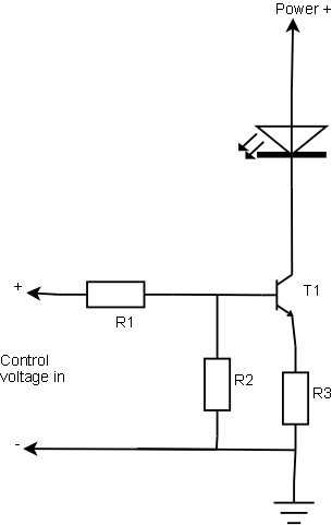
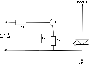
The following ramp signal generator is quite simple ramp generator based on discrete transistors which do some switching, capacitor and a constant current source made by using one transistor. The idea of the circuit is taken from N-channel light dimmer design made by Kari Hautio.
Ramp generator circuit
Trimmer R5 is used in controlling the ramp signal. If you have an oscilloscope, then it is best to use it to look at the situation so that the signal send by the circuit is what is described eariler. A good approximation is so start at position that R5 is set to it's center position.

Besides generating the ramp signal the sampl generator circuit works as a power supply comaprator part of the dimmer. The 13.5V unstabilized output is used to power the comparator section (that putput can be loaded up to 100 mA). The 10V stabilized voltage is used only for internal use in ramp generator (that stabilized 10V voltage can be also used for some extra low power circuitry which need 10V voltage, for example local dimmer controls if such thign are needed).
The ramp generator used a normal mains transformer which can output at least 200 mA of current, because it powers both ramp generator itself and the voltage comparator circuits. I relected a tranformer which has an invernal overload protection inside the transformer (overhating protection fuse), so I did not need to add any extra fuses for this transformer. If you use other kind of transformer, select a suitable fuse to protect it. In any case a 200 mA fuse on the secondary would be a good idea, propably also a primary fuse.
Component list for ramp generator:
R1     10 kohm 0.25W
R2 1 kohm 0.25W
R3 1 kohm 0.25W
R4 100 ohm 1W
R5 470 ohm trimmer
R6 10 kohm 0.25W
C1 2200 uF 25V electrolytic
C2 1000 uF 25V electrolytic
C3 2.2 uF 25V
D1-D5 1N4007
D6-D7 10V zener diode 1W
D8-D9 1N4148
Q1-Q3 BC547
TRANS Transformer 230V primary and 12V 200 mA secondary

Voltage comparators


| \      470 ohms   1N4148
0-10V input >-+------------|+ \
| | >-----/\/\/\----|>|--+
47kohm +---|- / |
| | | / TRIAC card
| | control input
| 100 Hz ramp signal |
| from ramp generator |
| |
Input ground --+--------------------------------------+- Logic ground
(ramp generator ground)
The circuit works so that the comparator output in low when the input voltage is higher than the ramp voltage. When the ramp signal voltage gets lower than the input voltage the comparator output goes high which causes that current starts to flow through resistor to optocoupler which causes the triac to cnoduct.Because the ramp signal starts at every zero crossing from 10V and goes linearly to 0V at the time of one half cycle the input voltage controls the time when the triac is triggered after every zero crossing. This effectively means that the control voltage controls the ignition phase of the triac. The output of the comparator is a pulse width modulated signal is is syncronized to mains voltage. The start of every PWM pulse changes the position depending on control voltage and the end is at zero crossing of mains votlage. The start of the pulse is used to trugger the output triac.
Because the dimmer has 4 channels, you need four of such units. A classical LM324 operational amplifier is very suitable to be used in this project, because it has four suitable operational amplifiers in one case. This part of the circuitry is powered from unregulated 13.5V voltage supplied by the ramp card. One ramp generator generates the operating voltage and the ramp signal for all four comparator channels.
The picture below shows the output signals the voltage comparator outputs to the triac card at different dimmer settings:
Comparator output waveforms
Component list for 4 channel comparator card:
4x     47 kohm 0.25W resistor
4x 470 ohm 0.25W resistor
4x 1N4148 diode
1x LM324 quad opamp

Triac output card

I used Velleman K2634 four channel triac card for the output card. The reason for using this card is that by using a good quality electronics kit I can get easily and quite cheaply a safe and easy to build mains voltage interface. Check the Velleman K2634 documentation for mode details on the kit.
I added small extra heatsinks to the triacs on the card to make them be able to handle 4 amperes per output without overheating.

R1                                      9V psu +
820 |
+---/\/\/\----------+ +----------------------+------------------------> 230V
+Vin 1| |5 | Hot bus
+=====+ IC1 +-+ | MT1
In | | Optoisolator | G\ |
10-15V |4N27 | Driver | ----- TRIAC
(10 mA current +=====+ | /\ \/ Q600 4F31
LED 2| |4 | -----
+-----|<|-----------+ | | | MT2
Ground \ R2 / |
/ 12K \ | hot
\ / R4 +-------FUSE-------+---> to load
/ \220R 4A |
| | |
| |/ T1 |
+---------------| BC547 |
| |V --- C1
\ \ --- 47 nF 250V
/ R3 | | (X2 rating)
\ 10K | \
/ | / R5
| | \ 100 ohm
+-----------------+---- 9V psu - / 3W
|
| neutral
+-+--> to load
|
|
+----> 230V
Neutral bus
The triac card contains four controlling circuits similar to circuit shown above fitted into one circuit board (provided by Velleman). Each output channel triac needs it's separate small heatsink to be able to handle full 4A current (around 1A maximum withouth heatsink). Those heatsinks are not allowed to touch each other unless they are isolated from the triac case (in my prototype they were not).
Each output is protected with 4A fuse, which should be fast type to give at least some kind of protection to the triac against overload. Pleace note that even a fast fuse does not make this output short-circuit proof, so if you happen to short the output, you quite propably loose both triac and the fuse (in some fortunate cases you might only burn the fuse).
This part of circuitry needs it's own power supply of 9V for generating the triac trigger pulses. This power supply must be separate from any other power supply in the quipment, because one end of the this 9V voltage is directly connected to mains input. Each triac controlling circuitry needs around 50 mA, so you need around 200 mA total.
The LED shown in the circuit diagram was wired so that it is visible on the dimmer front channel. It is very useful to monitor the state of the dimmer channels.
The components R5 and C1 make an output filter for the circuit to handle highly inductive loads better than without it. The circuit can be built without them, but this might cause some problems with some inductive loads.
Component list for single output channel (4 total needed for complete dimmer):
R1     820 ohm 0.25W
R2 12 kohm 0.25W
R3 10 kohm 0.25W
R4 220 ohm 0.5W
R5 100 ohm 3 W
C1 47 nF 250V (with X2 rating approved for mains filtering)
T1 BC547
IC1 4N27 optocoupler
LED Red LED
TRIAC Q600 4F31
FUSE 4A fast acting fuse

9V power supply for triac card


230V:8V@200mA

LIVE ------FUSE---+ +-----+ +------+-------- +
32mA )||( | |+ |
230VAC )||( BRIDGE === 4700uF 9V DC
)||( RECTIFIER | 25V to triac card
)||( | |- |
NEUTRAL ----------+ +-----+ +------+-------- -

This power supply is an unregulated and very simple power supply. This is only used by the triac card to operate the circuits between triac gate and the optoisolator. This power supply must be separate from all other power supplies in the dimmer, because then the 9V output is connected to the triac card it becomes to float at mains potential (the 9V input + in triac card is in direct connection with mains live wire).The primary fuse size was selected to be the smallest I could easily find. This transformer had also interhanl overheating protection so it is not a bad thign that the fuse is few times bigger than needed (just protects against severe short-circuits, not constant small overload). If you want better transformer protection, use 200 mA secondary fuse.
9V power supply components:
C1     4700 uF 25V electrolytic
RECT Bridge rectifier 1A 100V
TRANS Transformer 203V primary and 9V 200 mA secondary
FUSE 32 mA slow fuse

Mains power section


LIVE  ---FUSE----+-----------+----COIL-------- Live to triac card
10A | | 50uH
| | (10A)
230V AC === 470 nF |
50 Hz | 250V X2 +--
| To transformers
| +--
| |
NEUTRAL ---------+-----------+---------------- To neural bus on triac card

GROUND --------------------------------------- To ground pins on output connectors

This mains power section consists of 10A fuse which provides a protection agains the overloading of the mains input connector (10A grounded IEC male) and the filtering coil. In first prototype I used a normal 10A 5x20 mm fuse, but I later updated that to an automatic resettable 10A fuse (standard DIN mountable as used in distribution panels). The main fuse is designed to be an overload protection (for wiring, connectors and overheating protection), so it does not beed to be particaly fast (the outputs with surge scurretn ensitive triacs have their own separate fuses for their protection).This mains section includes a coil and capacitor which act as interference filters. That coil limits the surge current which happens when an output triac is turned on in the middle of the main cycle (as done in dimming). The capacitor between the mains live and neutral is a filtering capacitor to filter out the RFI which is still left after the coil.
Components for mains input filter:
C1    470 nF 250V capacitor with X2 rating
COIL 50 uH filtering cils which withstands 10A current
FUSE 10A resettable circuit breaker
Note: This filter circuit does not have any discharge resistor for capacitor C1 because in this circuit the transformers in the circuit take case that the capacitor get discharged immediatly after the power is removed from the circuit and no dangerous voltages are present in C1 when the circuit is not powered up.

Input connector

You can use practically any kind of connector for the 0-10V control input for the dimmer. I used a 5 pin DIN connector on my prototype. Suitable pin arrangement for 5 pin DIN connector is following:
Pin 1 = Channel 4
Pin 2 = Ground (common for all channels)
Pin 3 = Channel 1
Pin 4 = Channel 3
Pin 5 = Channel 2
Here is the pinout of 5 pin DIN connector:5 pin DIN pinout

Output connectors

The prototype I build used 4 grounded IEC female connectors and one 8 pin round Bulgin P552 connector (lighting industry standard). Both of those connectors are connected in parallel, so it is possible to use either one one them or both of them at the same time.
Connection of the IEC connectors:
IEC      Place in circuit

LIVE Output from channel triac on triac card
NEUTRAL Neutral bar on triac card
GROUND Wired to the mains input connector ground
Wiring for 8 bin Bulgin connector:
1   Ground
2 To channel 1 output triac
3 To channel 2 output triac
4 To channel 3 output triac
5 To channel 4 output triac
6 Not connected
7 To neutral bus
8 To neutral bus

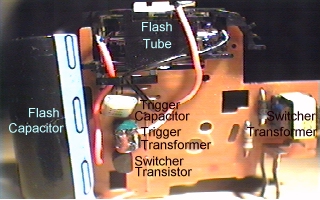
Circuit construction

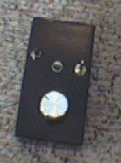
The whole circuit is built inside a convient plastic box which was previously used for some old outdated project. The picture below shows the internal construction of the dimmer unit.
Internal view of dimmer electronics
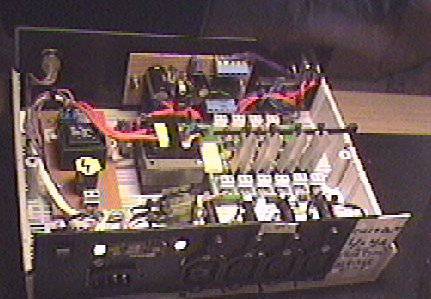
On the to of the picture you can (fron left to right) see power on indicator light, main controlling board (ramp generator+voltage comparators) and on the right you can see the 0-10V input connectors.
On the middle section on the picture (from left to right) you can see the following items: 9VDC power supply for triac card, 12VAC transformer for main control board and on the right the triac switching card (the one with four heatsinks).
On the bottom of the picture you can see the power input connector, filtering capacitor, output connectors+protective fuses and the filtering coil on the right. All of the power connectors are 10A IEC connectors for the reason that bigger connectors (like SCHUKO mains sockets) don't fit nicely to the back panel of the circuit.
After I took this picture I have added the automatic resettable 10A main fuse and 8 pin Bulgin connector to the back panel of the dimmer. I added those for my convience. Now I can change or reset the fuses without opening the case. And one connector handling four lamps is very convient in cutting the mount of needed cables on the lighting system
The circuit construction has beed used for controlling up to 2 kW of lights for many hours without any heating problems. If in any doubt with our circuit cooling needs please add an overheating protector to the circuit.

Circuit safety and compliance

This circuit design has not been tested against any safety or EMC standards in effect in Europe which would apply to this product. I have tried to make this circuit design to be safe and not to cause too much interference to other equipments.
The electrical safety of the circuit is provided by using adequate wiring (well insulated 1.5 mm^2 for main current carrying wires, 0.75 mm^2 for other mains wires), adequate insulation (insulted wires, plastic case), ehough distance on the circuit board between tracks), using proper fuses and good enough mechanical construction. The plastic case provides mechanical protection (not possible to touch mains carrying parts) and provides double insulation. The mains switching parts it done using a ready made design (Velleman kit) which is designed for this kind of appications, so it's construction should be safe (it looked a good design). My own other parts were operated by low voltage provided by good quality mains transformers (doulby insulated). Overheating protection is provided by providing large enough heatsinks for triacs and using case with some ventilation holes and testing the whole system with hours of full load (no too much heating noticed in any tests).
EMC issues are another story, which are not to be tested easily. I am not completely sure under which EMC standard the circuit would fall-in, but IEC/EN61000 might be that. According some disuciions in usenet news on those topics it seems that general light dimmers up to 1 kW do not need to be tested for power harmonics and same applies to professiona light dimemrs up to 3680 W. So the power harmonics issue should be handled right.
Commercially made light dimmers need to meet conducted emission standards. EN55015 standard set the limits for conducted emission on dimmer products. The conducted emissions are mostly harmonics and can exist up to megahertz frequecny region. I use one choke and filter capacitor on the power input approach to reduce emissions conducted throught the power input to the mains input wire (propably the longest wiring connected to the equipment). The output does not have any specific filtering in them. The coil in the input limits somewhat the current rise on them, but I don't know if the emissions there are within the limits set by the standard or not.
For example NJD electronics seem to list the following standards for one ot their light sequencer circuit: EN60065 (European Standard for Electrical Safety) and EN55103 (European Standard for Electromagnetic Compatibility) for example for a light sequencer circuit. Some DM1000x rack mountable dimmer from NDJ Elecronics lists the following standards: EN60439 Part 1 (European Standard for Safety of Electrical Switchgear), EN55015 (European Standard for Electromagnetic Compatibility) and EN60297 (Fascia panel dimensions).

Using the circuit

I have used this circuit vith quite wide variety of the lights. The circuit is designed to work with normal light bulbs. The circuit is not designed to operate with highly inductive loads, but seems to be able to at least somehow control some halogen light driven by a normal transformer.
Because the circuit takes a standard 0-10V input it can be used with practically any professional lighting desks which has standard 0-10V output.
If you are looking for something cheap, then you can build my 4 channel simple analogue light controlling desk which has performed very well with this dimmer circuit (propably even install one on the fornt panel of the case). The dimmer rack has been in use in some parties controlling up to 1600 watts of lights. At that load the heating of the dimmer was not a problem at few hours of constant use at near full power output.

Known features and problems

I have tested the dimmer circuit with wide variety of different loghting loads and dimmer seemed to work quite well with them. I have successfully dimmed also inductive loads like low voltage halogen lighting with transformer in them. The only annoying feature on my first dimmer prototype (no R5 and C1 filter) was that on some cases very capacitive or inductive loads have caused some false operation on nearby dimmer channels. I have found (quite rarely though) that certain highly inductive loads when connected to one channel and dimmed to certain level can cause other channels normally set off to turn on. This hasl also happened few times with channesl which have had long cables connected to them but no light bulbs in them. When I have been dimming normal light bulbs I have not noticed any problems with this version.
After experimenting seems that that the triacs might need some extra filtering on output side to avoid this kind of problems with certain problematic loads. WIth experimenting and looking at other dimmer desing I decided to add R5 and C1 to the circuit to add tis filtering. It seems to have solve the problem and work otherwise well.

Modifications I have done later to my unit

I have done several modifications / additions to the circuit I built. The basic circuit operation has stayed the same, but there are few things that had made the circuit easier to use.
First thing was to replace the 10A mains fuse, that was originally placed inside the circuit (hard to change) with a 10A resettable circuit breaker. I though this would be more convient as the main overload protector.
In the beginning the circuit had only IEC output connectors. I added a 8-pin Bulgin P552 connector to the circuit back panel. This connector allows connection of all four output channels with only one connector. This allows this dimmer to be used with disco light setups that use this connector. This 8-pin Bulgin connector is just simply wired electrically in parellel with the existing output connectors.


Modifying the circuit for 120V 60 Hz operation

Due the large number of request for information how to modify the circuit for 120V 60 Hz AC operation, I have included this chapter to answer most of the questions so you don't need to mail me to ask for details.
To use the circuit with 120V 60 Hz AC you will have to do atleats the following modifications:
  • Ramp generator
    • Change transformer to a model with 120V AC primary and 12V AC secondary and use suitable fuse for it
    • Tune the R5 using the same instructions as for 50 Hz operation, 60 Hz operation needs a different position for R5, but the tuning range is wide enough for this and same tuning procedure applies after you have connected the dimmer to 60 Hz power.
  • Voltage comparators
    • No modifications needed
  • Triac output card
    • Velleman K2634 four channel triac card is designed to operate with any voltage from 12V to 230V, so no modifications for this is needed
  • 9V power supply for triac card
    • You need to use 120V to 8 V AC transformer
    • No need to change fuse rating
  • Mains power section
    • No changes needed here
  • Output connectors
    • No changes needed here unless you want to use some other kind of connector for output
There is no guarantee that those were the all necessary modifications or entirely the right ones. They are my quite quick analysis what needs to be done. I have not tested those modifications and there is no guarantee that that folloging those gives you any usable or safe results.
Related Posts Plugin for WordPress, Blogger...