
Not a real project this time, most likely an implementation of another person project.
If you like to play videogames in your computer as much as I do, you probably already heard about the MJoy, which is an USB joystick made by Mindaugas that uses an ATmega8 and have 24 buttons, one hatswitch (or POV or D-Pad depending on the game) and 6 analog axes.
It’s oriented to flight simulators games, but can be used for any game, it’s should work wonderfully if you are trying to build a MAME cabinet (Uh, I might try that later).
And it can do that with really simple components, just some resistors, 12 MHz crystal, zener diodes and some diodes to prevent phantom keys (and of course, an ATmega8).
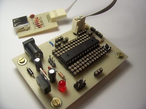
Anyway, since I was already etching the beta board myself, I made a little board for this implementation.
But this part is so simple that you can do it in a protoboard or perfboard.
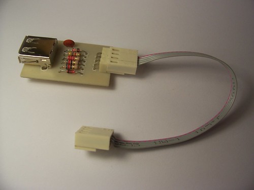
And I know, I know, I should use a B USB connector since it’s a downstream device, but I couldn’t find one, so I used a female A USB connector and a male-to-male A cable.
Unfortunately, Mindaugas site was been down for ages, and people who wish to build one depend on web.archive or the first version of the project, since its still on its original place.
So I will post the code here, but as soon as the site is back I will remove it.
I used the alternative version, made by LazyCamel, but you can try any version to see if it works for you (aren’t you glad now that I put that general purpose connector on the beta card?).
Just put a 12 MHz crystal in the connector in the beta card, 22pF ceramic capacitors in the crystal capacitors place (if you don’t know here it is, just click in the top view photo of the beta card and then see the notes on flickr), always remember to connect Agnd to ground and Vref and AVcc to the positive power supply before you program the code.
Connect the ground on the USB board with the ground on the beta board, same with the 5V, then connect -D to pin 2 on the ATmega8 and +D to pin 3 and 4.
Program the code and then program the fuses, MJoy suggest that you should only program the SPIEN fuse, I suggest that you program the CKOPT fuse to, so it should something like this on PonyProg.

That should be it.
Any doubt, take a look at the schematics that LazyCamel made, there is even a board there, so you shouldn’t have any problems.
The code in hex from LazyCamel
The pdf from LazyCamel with the schematics and the board that he made.
The pdf from LazyCamel with the schematics and the board that he made.
The schematics and the board file in eagle format with the B-female USB connector.
The schematics and the board file in eagle format with the A-female USB connector.
The schematics in PNG.
The schematics and the board file in eagle format with the A-female USB connector.
The schematics in PNG.
The board is released as-is under
Creative Commons 3.0 - Attribution - Share Alike
Creative Commons 3.0 - Attribution - Share Alike
No comments:
Post a Comment